Compensator

a compensator and compression technology, applied in the field of oil and gas drilling, can solve problems such as the loss of drill string compensation, and achieve the effect of reducing capacity and eliminating the risk of losing compensator capabilities in “fixed-to-bottom” operations

Active Publication Date: 2014-09-04
MHWIRTH
View PDF6 Cites 9 Cited by
  • Summary
  • Abstract
  • Description
  • Claims
  • Application Information

AI Technical Summary

Benefits of technology

[0017]Thus, by utilizing the combination of an active compensated drawworks and a passive top compensator having a reduced capacity compared to conventional top compensators, the risk of losing compensator capabilities in “fixed-to-bottom” operations is eliminated. The active compensated drawworks will handle operations where the drill string is not “fixed-to-bottom”. In this mode the passive motion compensator is not in use and the crown block is resting on the water table, such that the loads are transferred directly into the derrick and not through the passive motion compensator.

Problems solved by technology

However, having the riserless drill string in a fixed-to-bottom configuration is a precarious condition, in that the well will become open to the surrounding seawater if the drill string should fail, for example due to compensator malfunction.
An active compensated drawworks is also susceptible to mechanical malfunction, leading to a compete loss of drill string compensation.

Method used


Image

  • Compensator
  • Compensator

Examples


Embodiment Construction

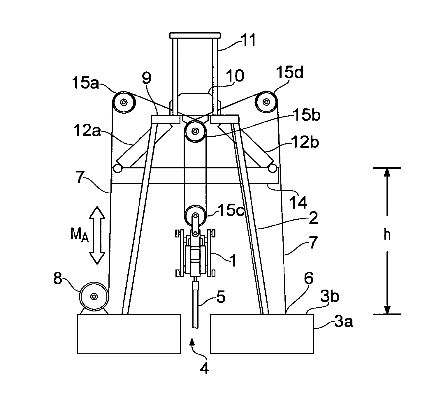
[0021]FIG. 1 is a schematic illustration of the motion compensator system according to the invention in an active mode. A derrick 2 is supported by a floating vessel (indicated schematically as 3a) having a deck structure 3b. A drilling machine 1 is suspended by the derrick and controls a drill string 5 extending through a moon pool 4 and, into the water and to the seabed (not shown). This arrangement is well known in the art.

[0022]The drill string 5 is suspended by a crown block 10, via the drilling machine 1 and a wire-and-sheave arrangement 7, 15b,c. In this active compensation mode, the crown block 10 is resting on, and preferably bolted to, a watertable 9 in the derrick. A drawworks 8 is connected to the deck structure 3b and to the drilling machine 1 via a wire 7 running through sheaves 15a-d and to a connection point 6 on the deck structure (required power and control devices, hydraulic hoses, etc., have been omitted from the figure, as these items are well known in the art)....


PUM


Abstract

A motion compensation system is provided for controlling relative movements between a floating vessel and an elongate element, where the elongate element is suspended by the vessel at a first end and extends into a body of water below the floating vessel. An active motion compensator is connected to the elongate element first end via an element arranged in an upper region of an erect support structure and a passive motion compensator is connected to the elongate element first end via the element. The motion compensators are structurally and operationally separate and independent units and are configured for separate and mutually independent operation.

Description

FIELD OF THE INVENTION[0001]The invention pertains to oil and gas drilling, and related operations, from floating structures. More particularly, the invention concerns a motion compensation system as set out in the preamble of claim 1.BACKGROUND OF THE INVENTION[0002]Floating vessels (ships, platforms, etc.) are commonly used for drilling, servicing and maintenance of subsea oil and gas wells. Typically, a riser is suspended underneath a drill floor and extends to a subsea wellhead on the seabed. A drill string may be suspended by the drilling derrick and run inside the riser, through the wellhead and into a subterranean hydrocarbon reservoir. The distance (and hence drill string length) between the seabed wellhead and the reservoir may be considerable. In this configuration, the riser is fixed to the seabed (via the wellhead), while the drill string is not. A malfunctioning drill string or drill string compensator will therefore normally not compromise the integrity of the well, as...

Claims


Application Information

Patent Timeline
Patent Type & Authority Applications(United States)
IPC IPC(8): E21B19/09
CPCE21B19/09E21B19/004E21B19/006
Inventor POHNER, LARS
Owner MHWIRTH
Why Eureka
Try Eureka