Method for producing a fork arm, and fork arm

a technology of fork arms and forks, which is applied in the direction of laser beam welding apparatus, electron beam welding apparatus, lifting devices, etc., can solve the problems of very low energy supply and very rapid progress of fork arms, and achieve high strength, low energy supply, and high welding strength.

Active Publication Date: 2014-09-04
EBW LEX GMBH
View PDF2 Cites 16 Cited by
  • Summary
  • Abstract
  • Description
  • Claims
  • Application Information

AI Technical Summary

Benefits of technology

[0007]It is an object of the invention to provide a method for producing a high-strength fork arm which is as light as possible and can be produced in an economic manner, and for which the disadvantages of the prior art are eliminated at least to a large extent. In particular, the production shall also proceed very rapidly, wherein, on the other hand, energy supply is very low.
[0011]The invention offers the advantage that despite low energy supply, high-quality fork arms can be produced, wherein the aforementioned disadvantages of the prior art are eliminated.
[0012]The crystalline structures of the entire fork arm and the individual steel lamellas remain largely undamaged even after welding. Due to the high power density of the electron beam welding or laser welding process, the welds are very narrow, (preferably less than 1 mm), but, on the other hand, they are deep (up to 100 mm) so that a high-strength planarly extending connection between the lamellas is achieved without additional material supply. The strength of the welds is so high that a weld depth of 30% of the fork arm width is sufficient for producing a super high strength fork arm that corresponds to the strength potential of the super high strength sheets of the individual lamellas with a tensile strength of, for example, 1500 N / mm2. However, the weld depth can be reduced or increased as needed. For example, the 30% mentioned above are divided into 15% on each of the side surfaces of the sheet metal lamellas. Taking account of a minimum bending radius specified by the manufacturer of the metal sheets, the metal sheets can be bent cold.
[0013]By using a CNC control, the invention is suitable for producing in large quantities, wherein due to the low energy input, the production costs can be reduced considerably.
[0014]The high welding speed (20 m / min) allows a production speed in intervals of a few minutes because a plurality of lamellas can be welded at the same time.

Problems solved by technology

In particular, the production shall also proceed very rapidly, wherein, on the other hand, energy supply is very low.

Method used


Image

  • Method for producing a fork arm, and fork arm
  • Method for producing a fork arm, and fork arm
  • Method for producing a fork arm, and fork arm

Examples


Embodiment Construction

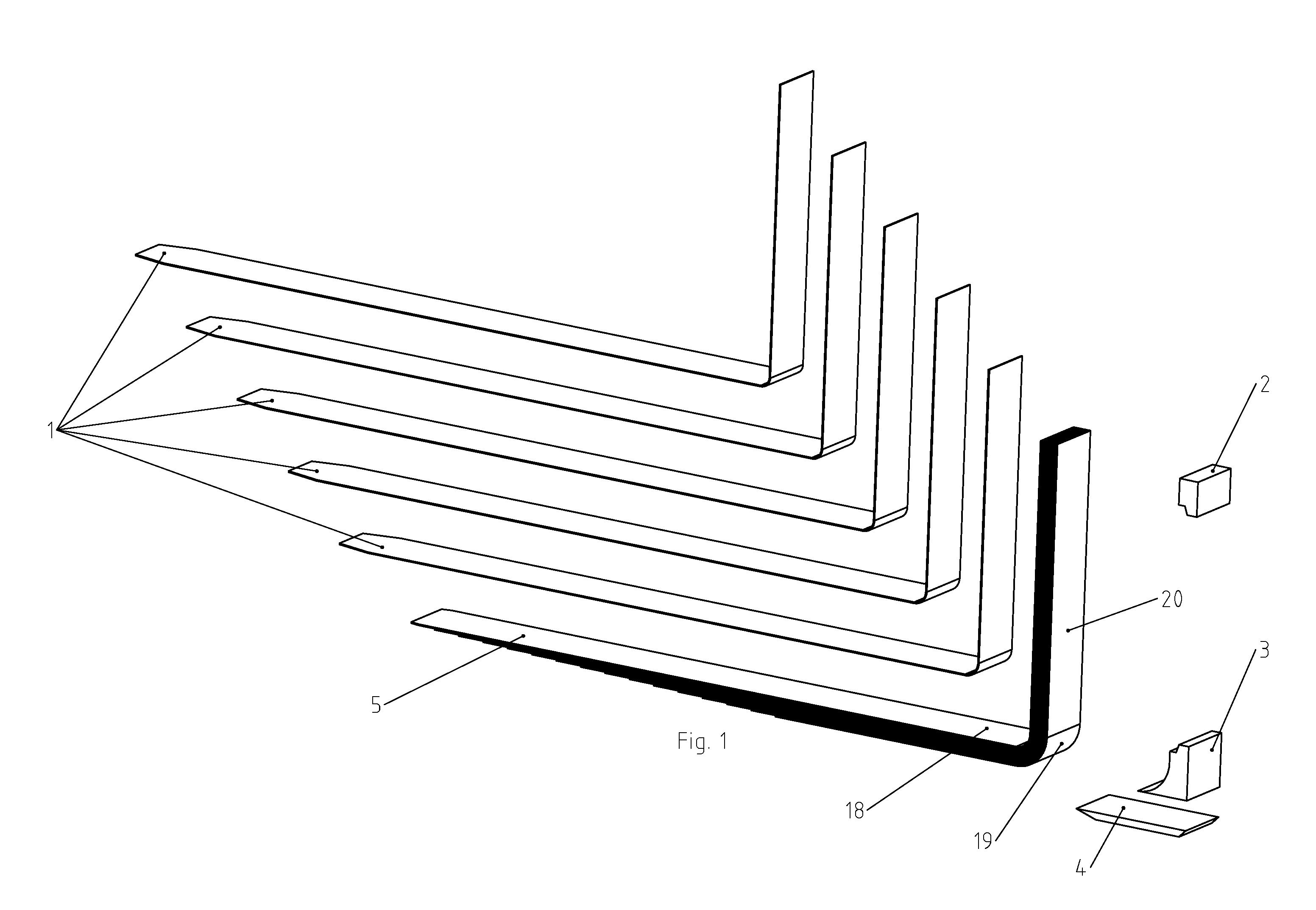
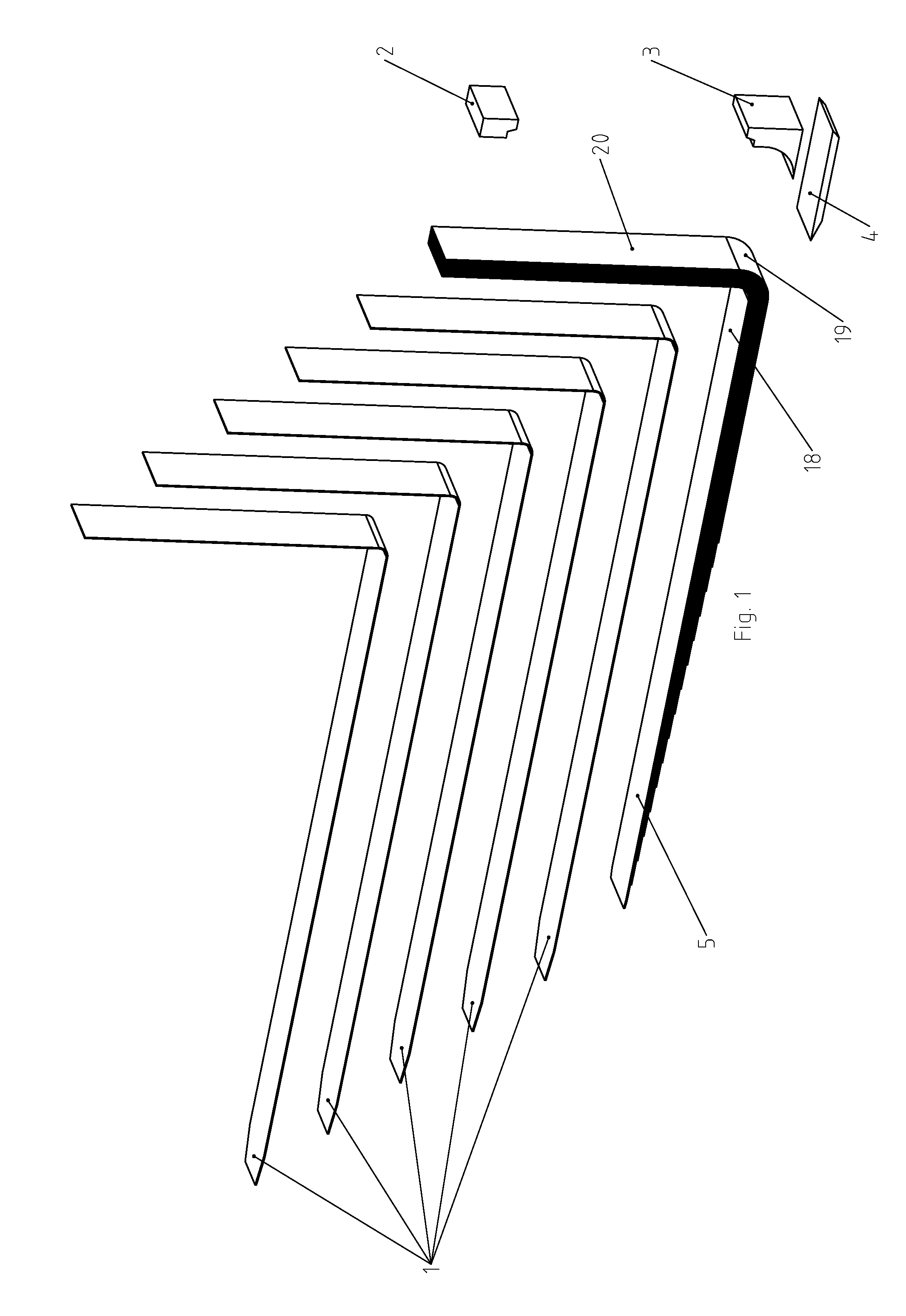
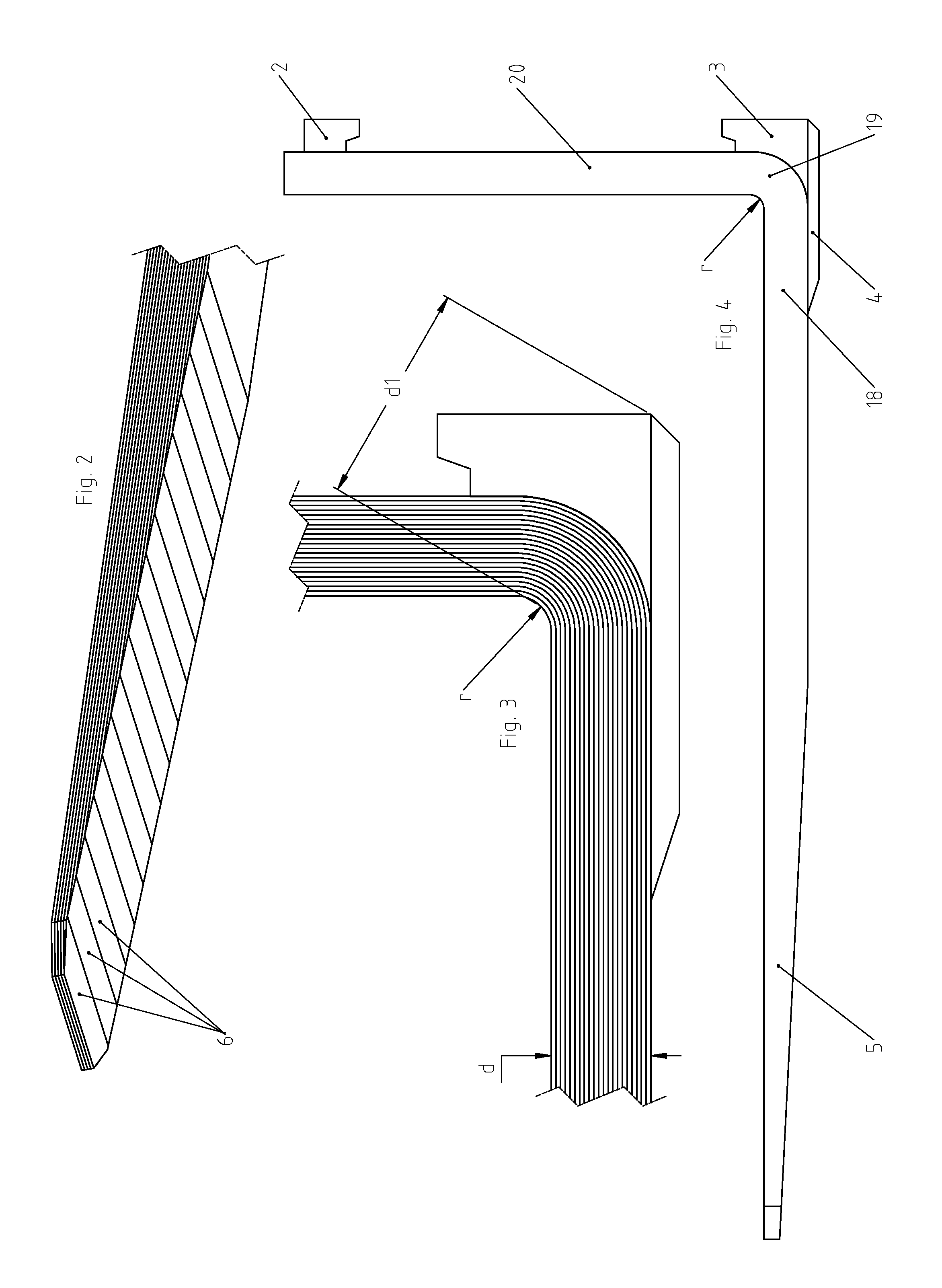
[0032]FIG. 1 shows the perspective exploded view of a first embodiment of a fork arm 18 in steel lamella construction, wherein each individual lamella 1, for example made of Docol 1500 M (with a tensile strength of 1500 N / mm2), is used with a sheet thickness (for example 2 mm) that allows cold bending without any problems. The fork blade 5 of the fork arm 18, which fork blade is substantially horizontal in the position of use, transitions via a fork bent 19 into a vertical fork back 20. As yet to be explained below, the individual lamellas 1 are welded together at the edge by electron beam welding, wherein the weld penetrates with a depth of at least 3 mm between adjoining surfaces of the parts.

[0033]Since the strength of the welds is very high, a weld depth of 30% of the fork arm width is sufficient for producing a high-strength fork arm. However, the weld depth can be reduced or increased as needed, wherein welding through the entire width of the fork arm is also possible.

[0034]Th...


PUM

PropertyMeasurementUnit
depthaaaaaaaaaa
depthsaaaaaaaaaa
tensile strengthaaaaaaaaaa

Abstract

A method for producing a fork arm (18) for load-carrying devices, said fork comprising a fork blade (5) which is substantially horizontal in the operating position, and a substantially vertical fork back (20) that connects via a fork bend (19) to said fork blade and is provided with connection elements (2, 3) for the conveying device, wherein the fork arm consists of a plurality of parts (1; 2, 4, 8, 9, 11; 18′, 12 to 17) that are connected to one another, at least a number of said parts are welded to one another, and parts (1; 2, 4, 8, 9, 11; 18′, 12 to 17) of the fork arm are welded to one another by electron beam welding and / or laser welding, wherein the weld penetrates planarly with a depth of at least 15 mm between adjoining surfaces of the parts.

Description

BACKGROUND OF THE INVENTION[0001]The invention relates to a method for producing a fork arm for load-carrying devices, said fork arm comprising a fork blade which is substantially horizontal in the operating position, and a substantially vertical fork back that connects via a fork bend to said fork blade and is provided with connection elements for the conveying device, wherein the fork arm consists of a plurality of parts that are connected to one another, and at least a number of said parts are welded together.[0002]The invention also relates to a fork arm produced according to this method.[0003]A known fork arm is disclosed in DD 256 050 A3 and is shown and described there in the sole exemplary embodiment as consisting of three steel lamellas welded together at the edge by means of a fillet weld, wherein it is mentioned that the individual lamellas can be adhesively bonded to one another, but without suggesting a manner in which adhesive bonding can be carried out. The outer lame...

Claims


Application Information

Patent Timeline
Patent Type & Authority Applications(United States)
IPC IPC(8): B66F9/12B23K26/24B23K15/00
CPCB66F9/12B23K26/24B23K15/0006B23K15/0053B23K15/006B23K26/242B23K2101/006
Inventor SZLEZAK, PHILIPP
Owner EBW LEX GMBH
Why Eureka
Try Eureka