
Differential non-contact biopotential sensor

a biopotential sensor and non-contact technology, applied in the field of differential non-contact biopotential sensors, can solve the problems of inconvenient and practical application of gels, inconvenient subject-to-subject interaction, and inability to achieve the effect of reducing environmental or ambient nois

Inactive Publication Date: 2014-09-04
THALMIC LABS
View PDF4 Cites 82 Cited by
  • Summary
  • Abstract
  • Description
  • Claims
  • Application Information

AI Technical Summary

Benefits of technology

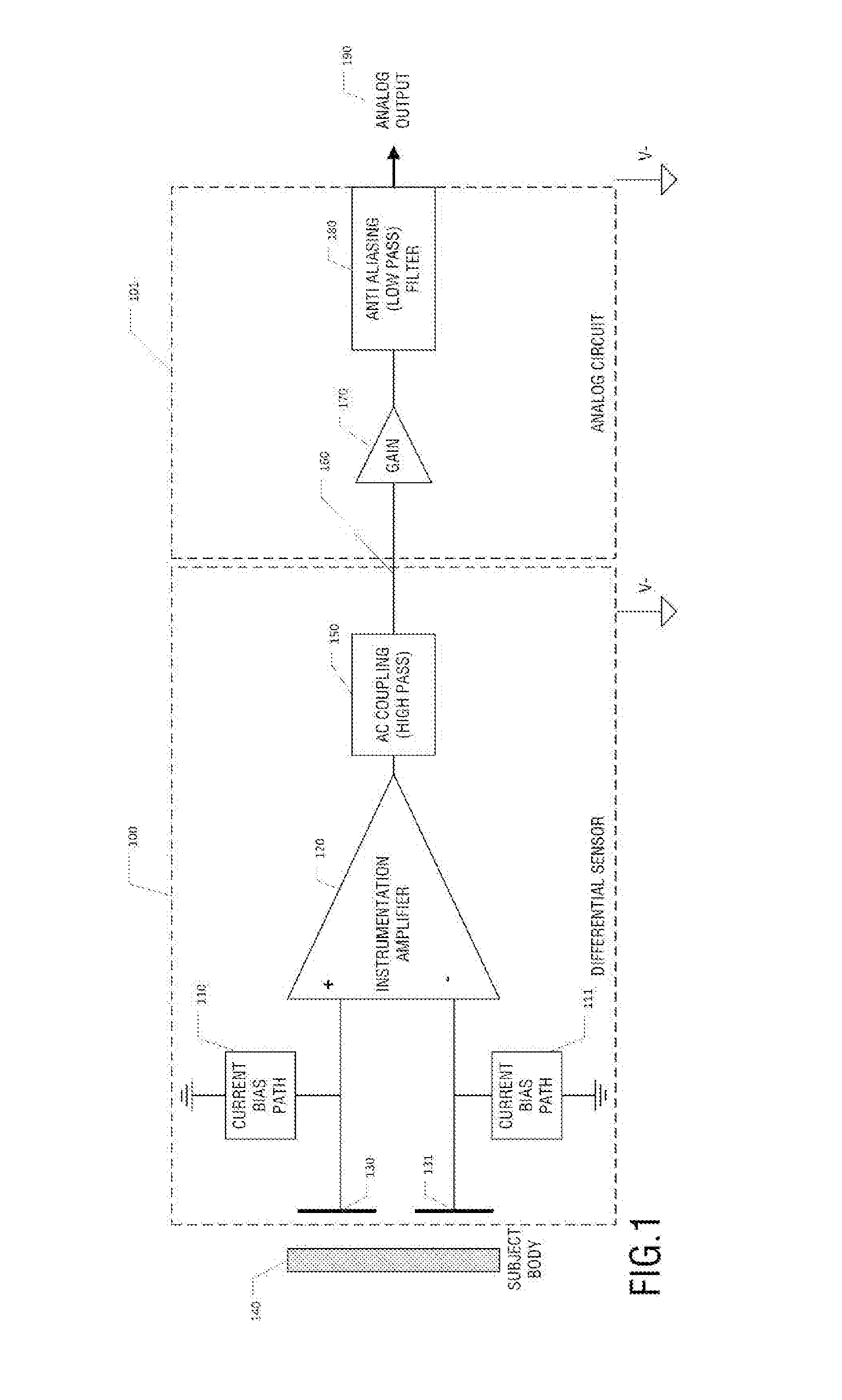
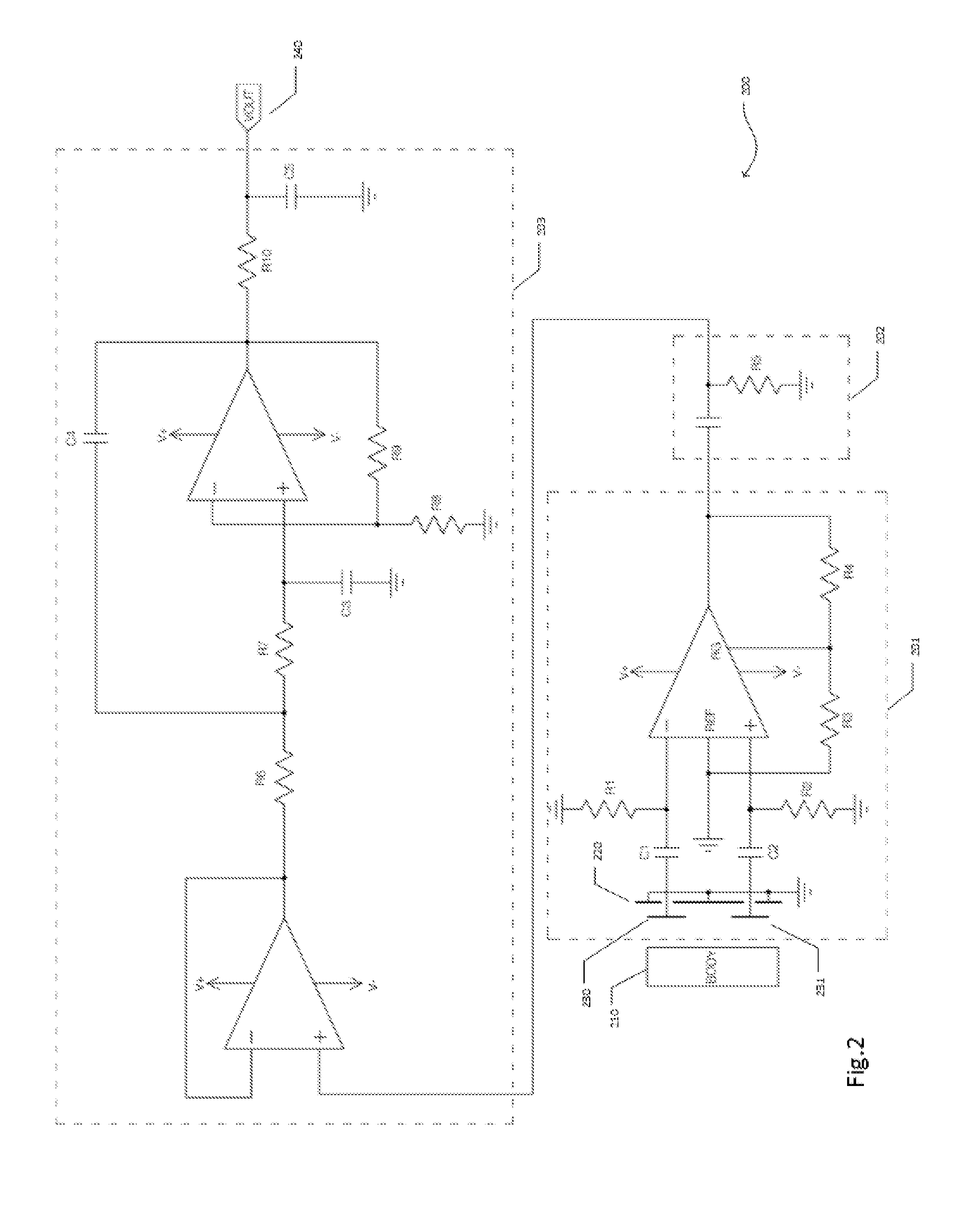
The invention provides a sensor system for measuring biopotential signals using two capacitive electrodes. The sensor produces a differential signal, which improves performance. The sensor is low-noise and measures electrical voltage signals from the body. Additionally, a method may include using an external shield to reduce ambient noise.

Problems solved by technology

Intramuscular EMG techniques are invasive, requiring insertion of a needle or electrode through the skin.
Applying a gel is both inconvenient to the subject and not practical for many situations where one may desire to measure biopotential signals.
When removed, the conductive gels leave behind a residue which requires further cleaning In applications where these signals are measure frequently, for example in a muscle-computer interface or for the monitoring of athletic performance, this process is impractical and problematic.
These types of dry contact sensors suffer from fluctuating signal magnitudes as the subject perspires or as the pressure on the sensor varies.
Often when first applied to dry skin, the output signals from dry contact electrodes are low in magnitude and noisy and then change after the electrode is left in contact with the skin for some time.
The subject's body and surrounding environment generally are very noisy due to emissions from power lines, computers, electrical equipment, radio frequency devices, and others.
In a biopotential sensor system, using two distinct sensors is not desirable because each sensor, as well as any filtering and amplification circuitry, and the interconnections between the sensors, adds noise to the system which may vary from electrode to electrode.
Therefore when the signals are finally subtracted to produce a differential measurement between the two electrodes much noise remains.
However, these electrodes still suffer from the same limitations as other dry-contact sensors mentioned above.

Method used


Image

  • Differential non-contact biopotential sensor
  • Differential non-contact biopotential sensor
  • Differential non-contact biopotential sensor

Examples


Embodiment Construction

[0028]Definitions

[0029]Unless defined otherwise, all technical and scientific terms used herein have the same meaning as commonly understood by one of ordinary skill in the art to which this invention belongs.

[0030]As used in the specification and claims, the singular forms “a”, “an” and “the” include plural references unless the context clearly dictates otherwise.

[0031]The term “comprising” as used herein will be understood to mean that the list following is non-exhaustive and may or may not include any other additional suitable items, for example one or more further feature(s), component(s) and / or ingredient(s) as appropriate.

[0032]The term “non-contact” as used herein means that the biopotential sensor is not required to be in contact with the body of the subject, however it is understood that the sensor may be also be used as a contact sensor if desired.

[0033]Biopotential Sensor

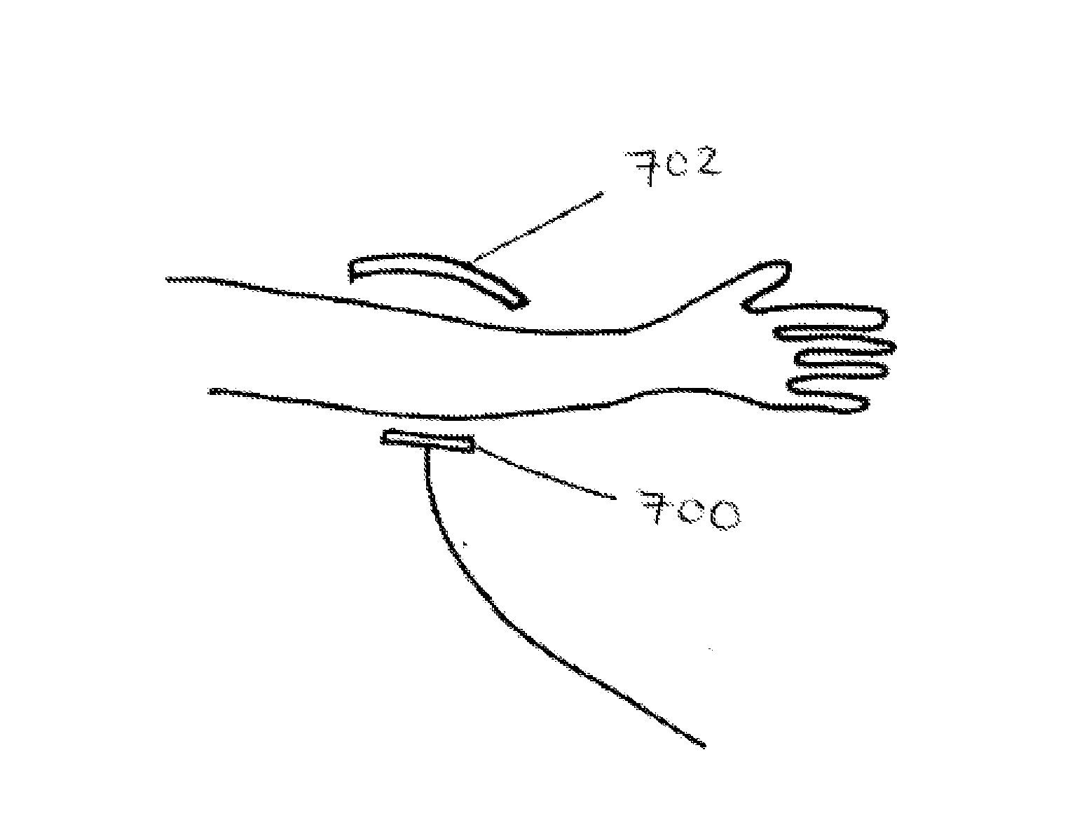
[0034]The present application describes a differential non-contact biopotential sensor for measuring b...


PUM


Abstract

A differential non-contact sensor system for measuring biopotential signals is described. The sensor is a low-noise, non-contact capacitive sensor system to measure electrical voltage signals generated by the body comprising two capacitive electrodes and outputting a differential signal.

Description

FIELD OF THE INVENTION[0001]The present invention pertains to differential non-contact biopotential sensors for sensing voltage signals generated by the body with a single sensor, and methods of use thereof.BACKGROUND[0002]Electromyography, or EMG, is a technique for measuring muscle response to nervous stimulation. EMG signals are generally measured using either surface electromyography (sEMG) or intramuscular EMG. Intramuscular EMG techniques are invasive, requiring insertion of a needle or electrode through the skin. Surface EMG is commonly collected using sensors placed on the surface of the skin, nearby the underlying muscle. Current sensors for measuring sEMG require direct electrical contact with the skin. The most outward layer of skin, the stratum corneum, is generally dry and offering low electrical conductivity. Therefore, to obtain a low-impedance electrical connection with the skin abrasion and / or conductive gels are applied to the skin below the electrodes. Applying a ...

Claims


Application Information

Patent Timeline
IPC IPC(8): A61B5/0492A61B5/00A61B5/296
CPCA61B5/7203A61B5/0492A61B5/7225A61B2562/0214A61B5/296
Inventor LAKE, STEPHENSERESHKEH, ALBORZ REZAZADEHBAILEY, MATTHEWGRANT, AARON
Owner THALMIC LABS
Learn More