High Altitude Aircraft, Aircraft Unit and Method for Operating an Aircraft Unit

a technology for aircraft and aircraft, applied in the direction of transportation hydrogen technology, transportation and packaging, energy-efficient board measures, etc., can solve the problems of balloon aircraft not being able to achieve the required extent of maneuverability, high cost and complexity of carrying out air space monitoring through satellites, etc., and achieves low drag, high lift, and high lift

Inactive Publication Date: 2014-09-11
AIRBUS DEFENCE & SPACE
View PDF15 Cites 60 Cited by
  • Summary
  • Abstract
  • Description
  • Claims
  • Application Information

AI Technical Summary

Benefits of technology

[0112]Using the high-altitude aerial vehicles according to the invention, an aerial vehicle formation can fly in a long-term operation of the flying components of the formation, comprising at least one high-altitude refueling aircraft and at least one high-altitude aerial vehicle carrying a payload, day and night, and at the required altitudes and speeds, in permanent operation.
[0126]The air space close to the ground and the ground can be monitored with substantially unlimited flying time as a result of the use of solar energy, and
[0127]solar-powered high-altitude flying can be maintained during the day and at night, in the summer and in the winter, with a substantially unlimited service life and a high payload proportion (such as 15%) of the flight weight.

Problems solved by technology

An essential problem of protecting a territory from hostile attacks today is to discover rockets, such as missiles, approaching this territory early enough so that effective combating of these rockets is possible.
Carrying out such air space monitoring by way of satellites is very expensive and complex.
Nevertheless, complete energy autonomy will not be achievable, so that such a high-altitude aircraft must also be supplied with external energy, which can be carried out by tanker aircraft, for example.
However, these balloon aircraft cannot be maneuvered to the required extent, both in terms of the altitude and in terms of the horizontal, and are thus not able, for example, to maintain a predefined position under the winds prevailing at these high altitudes.
Moreover, conventional aircraft are known, which have the required maneuverability, but allow only a very limited flight duration and cause very high operating costs in the process.
The wings of the aircraft had an extreme span of up to 30, and a very soft wing with large deflection, which made the aircraft very susceptible to gusts.
The Helios aircraft was lost as a result of a gust following extreme wing deflection due to structural failure.

Method used


Image

  • High Altitude Aircraft, Aircraft Unit and Method for Operating an Aircraft Unit
  • High Altitude Aircraft, Aircraft Unit and Method for Operating an Aircraft Unit
  • High Altitude Aircraft, Aircraft Unit and Method for Operating an Aircraft Unit

Examples


Embodiment Construction

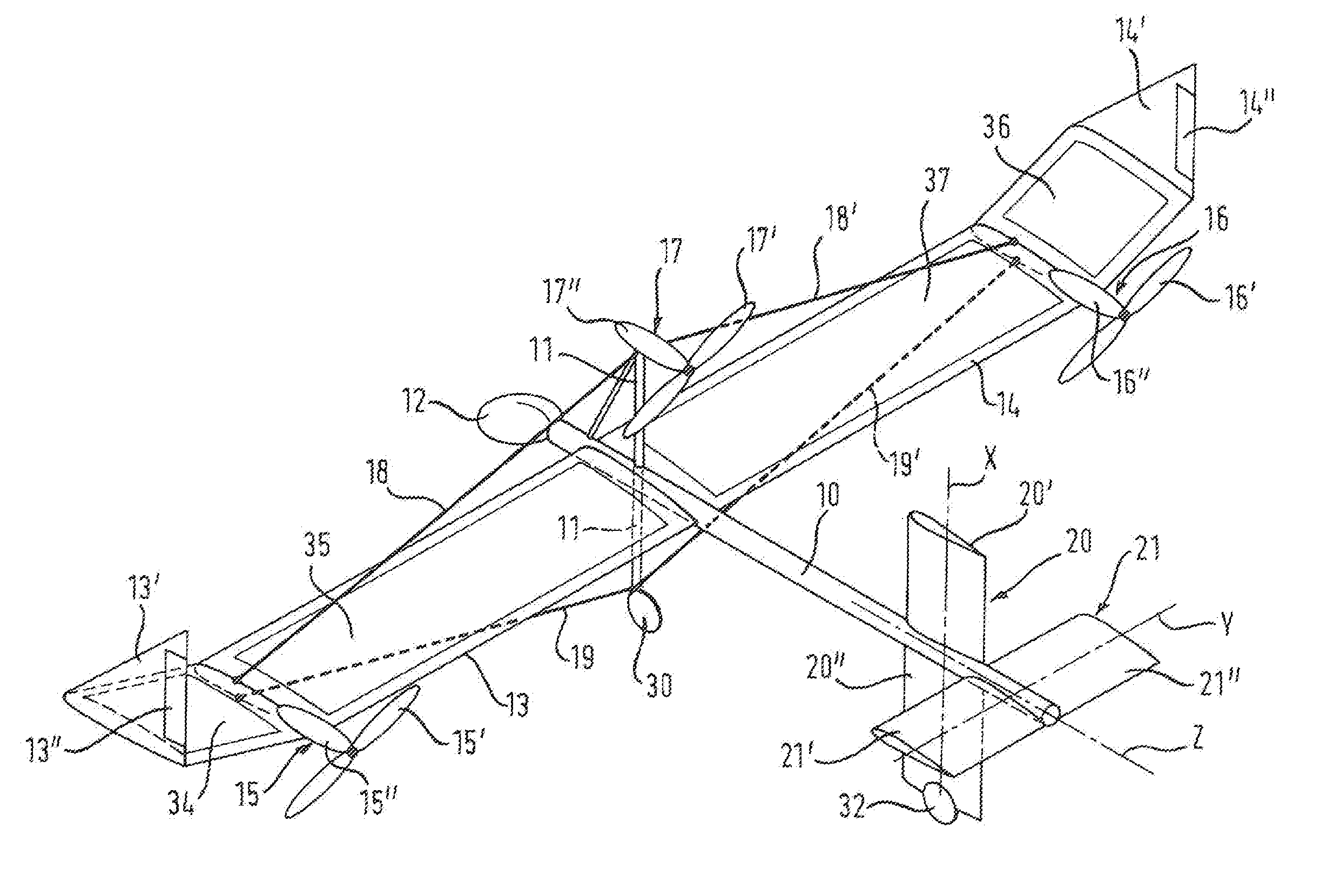
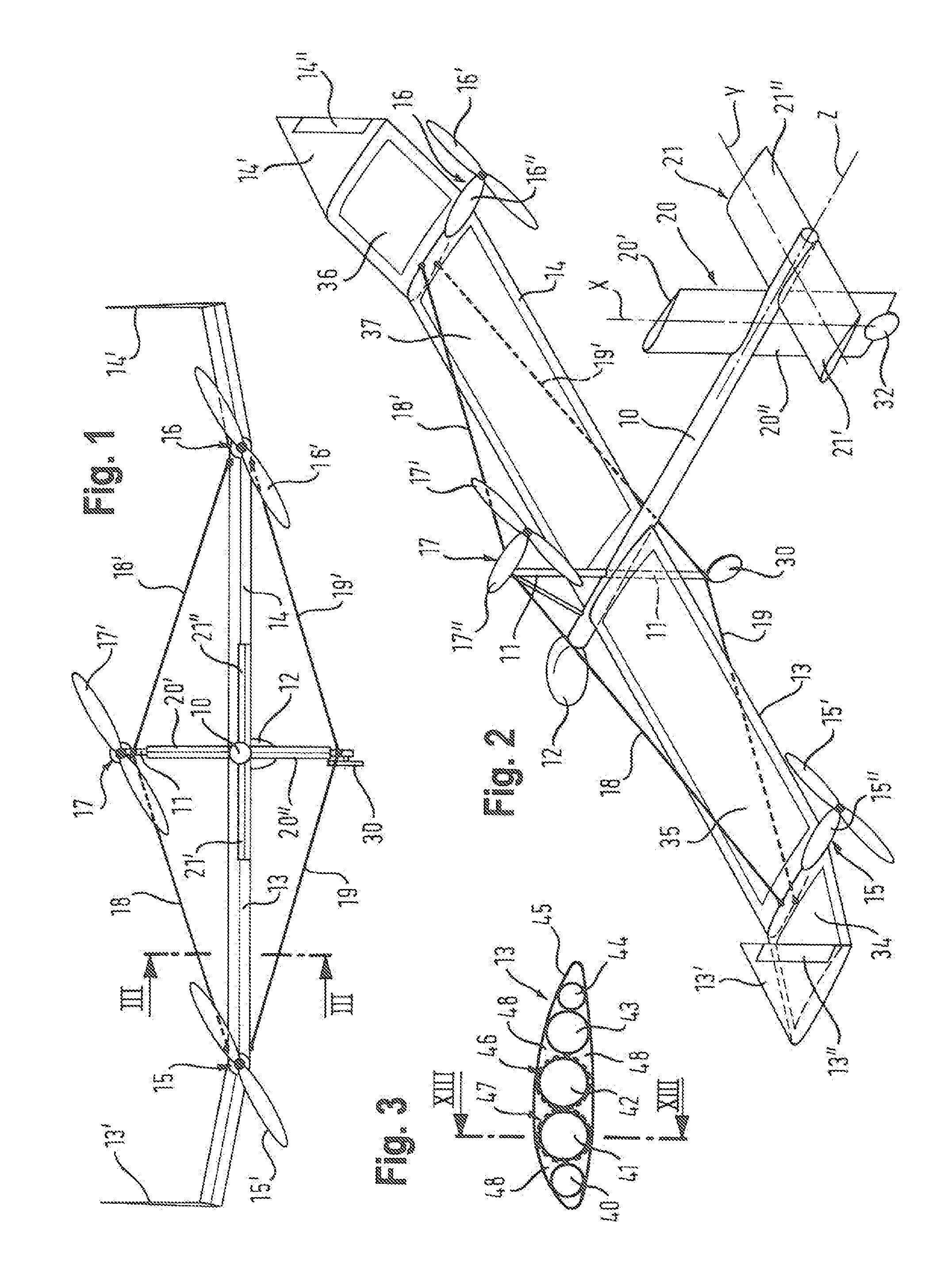
[0063]FIG. 1 shows a rear view of a high-altitude aerial vehicle according to the invention in the direction of flight. Two wings 13, 14 are provided on the side of a tubular fuselage 10 (FIG. 2), which has a balloon-like tip 12 at the fuselage nose. A substantially vertically extending winglet 13′, 14′ is provided at the free ends of each wing 13, 14. A propulsion nacelle 15, 16 is attached to each wing 13, 14 at approximately ⅔ the distance from the fuselage, each propulsion nacelle accommodating a motor 15″, 16″, which drives an associated propeller 15′, 16′ in each case. For example, a radar device can be provided in the balloon-like fuselage nose 12, which is designed as a radome.

[0064]A third propulsion nacelle 17 is attached to the top of a guyed pole 11 protruding upward from the wing. The third propulsion nacelle 17 also comprises a motor 17″, which drives an associated propeller 17′. While FIGS. 1 and 2 show the propellers 15′, 16′, 17′ as pusher propellers, the propulsion...


PUM


Abstract

A high-altitude unmanned stratosphere aerial vehicle includes a fuselage, wings, control surfaces, and a propulsion system including an engine and a propeller. Each wing has a plurality of hoses and wing spars extending in a direction perpendicularly to the longitudinal fuselage axis and are surrounded by a skin forming a wing covering that determines the cross-sectional contour of the wing, the cross-sectional contour forming a laminar flow airfoil that generates high lift when there is low flow resistance. At the free end facing away from the fuselage, each wing has a winglet extending transversely to the longitudinal wing axis. The winglet has a movable control surface, which allows an aerodynamic side force to be generated so as to bring the aerial vehicle to a banked position.

Description

TECHNICAL FIELD[0001]The present invention relates to a high-altitude unmanned aerial vehicle, in particular a stratosphere aerial vehicle, comprising at least one fuselage, wings, control surfaces and at least one propulsion system including at least one engine and at least one propeller. In particular, the invention relates to a high-speed, high-altitude unmanned aerial vehicle having its own solar propulsion system and additional fuel supply by aerial refueling with hydrogen gas from a solar-powered, lower-flying tanker aircraft, which produces hydrogen gas using solar energy by way of electrolysis from water the aircraft carries.[0002]The present invention further relates to an aerial vehicle formation comprising at least one first high-altitude unmanned aerial vehicle and at least one second high-altitude unmanned aerial vehicle, wherein the second high-altitude unmanned aerial vehicle forms a refueling aircraft for the first high-altitude unmanned aerial vehicle.[0003]Finally,...

Claims


Application Information

Patent Timeline
Patent Type & Authority Applications(United States)
IPC IPC(8): B64C39/02B64D39/00B64C27/41B64C9/00
CPCB64C39/02B64C27/41B64D39/00B64C9/00B64C3/30B64C39/024B64D2041/005B64D2211/00Y02T50/50Y02T90/40B64U30/12B64U10/25B64U2101/20B64U50/19B64U50/13
Inventor HIEBL, MANFREDPONGRATZ, HANS WOLFGANG
Owner AIRBUS DEFENCE & SPACE
Why Eureka
Try Eureka