
Ranging using wi-fi and ultrasound measurements communication

a communication device and ultrasound technology, applied in direction finders, instruments, acoustic wave reradiation, etc., can solve the problems of direct path us signal experiencing significant attenuation, easy inaccuracy of wifi-based ranging results, etc., to improve the accuracy of range measurement, improve the range determination between devices, and be easily deployed

Inactive Publication Date: 2014-09-11
QUALCOMM INC
View PDF0 Cites 71 Cited by
  • Summary
  • Abstract
  • Description
  • Claims
  • Application Information

AI Technical Summary

Benefits of technology

This patent describes a way to improve the accuracy of range measurements in devices using ultrasonic signals and wireless networks. By using existing components in devices like smartphones, this method offers a low-cost and easily-deployable solution. The use of ultrasonic signals allows for more accurate range measurements, especially in situations where there are multiple reflections or in non-line-of-sight topologies. By adjusting the detection threshold for ultrasonic signals, it is also possible to improve the range estimation of wireless signals. Overall, this patent provides a way to enhance the accuracy and precision of positioning in mobile devices.

Problems solved by technology

In contrast, WiFi-based ranging results based on RTT measurements of RF WiFi signals are prone to inaccuracies introduced by the granularity of the MAC clock or sampling clock.
In these situations, an US signal in the direct path may experience significant attenuation and there may be multiple strong reflections in the non-direct paths.
In addition, RF and US noise are uncorrelated, making it possible to select a much lower FTOA detection threshold for the combined likelihood of the two modalities to increase sensitivity of detection without increasing the probability of false-detects.

Method used


Image

  • Ranging using wi-fi and ultrasound measurements communication
  • Ranging using wi-fi and ultrasound measurements communication
  • Ranging using wi-fi and ultrasound measurements communication

Examples


Embodiment Construction

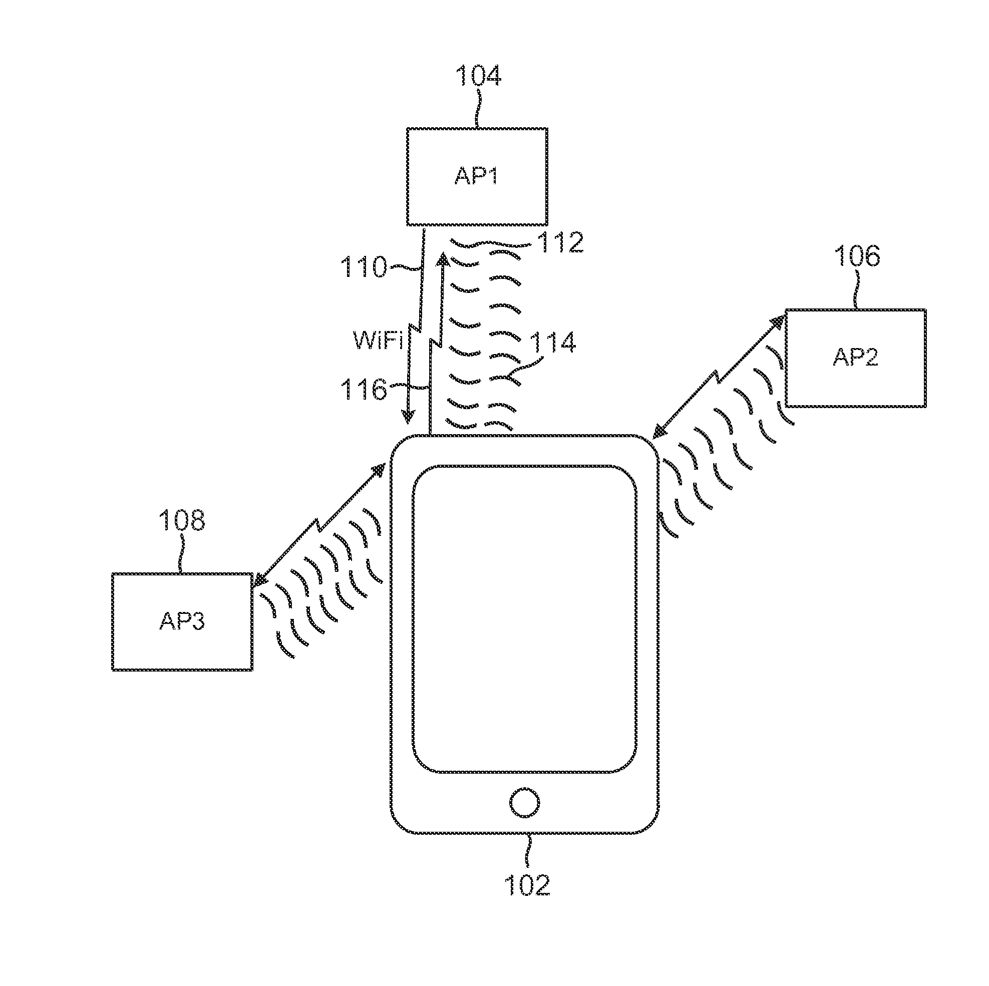
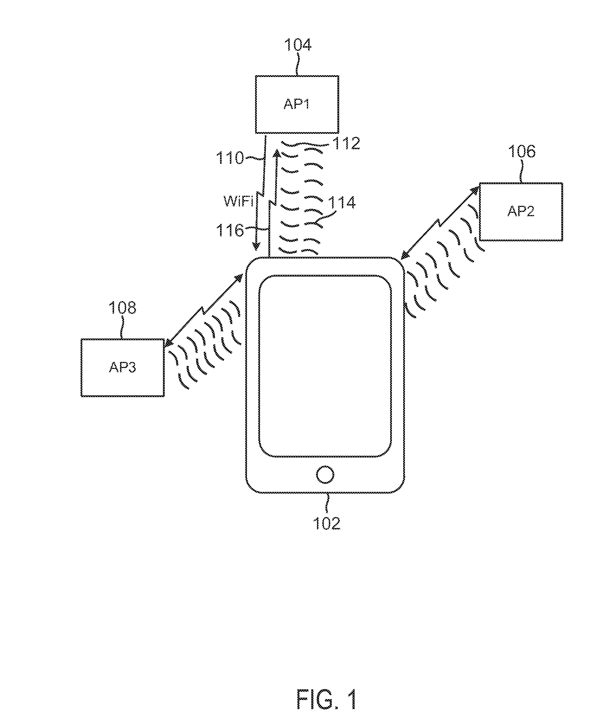
[0022]Systems and methods are disclosed to use US (ultrasonic) and WiFi signals to estimate the range between WiFi-enabled devices or to estimate the position of WiFi-enabled mobile devices in WiFi networks. The devices in the WiFi networks may leverage US-capable sensors already existing on the devices. For example, many speakers and microphones used in smartphone are capable of operating as US transducers to generate and receive signals above the human-audible range in the US frequency. APs (access point) in WiFi networks may also be fitted easily with US transducers if they don't exist already. In addition, transducer arrays may be installed to provide directional capability such as Tx (transmit) beam forming and / or Rx (receive) DOA (direction-of-arrival) estimation on WiFi devices.

[0023]US ranging between devices may be performed using RTT or one-way measurements. To enable US ranging between a device and multiple US transmitters simultaneously, e.g., between a mobile device and...


PUM


Abstract

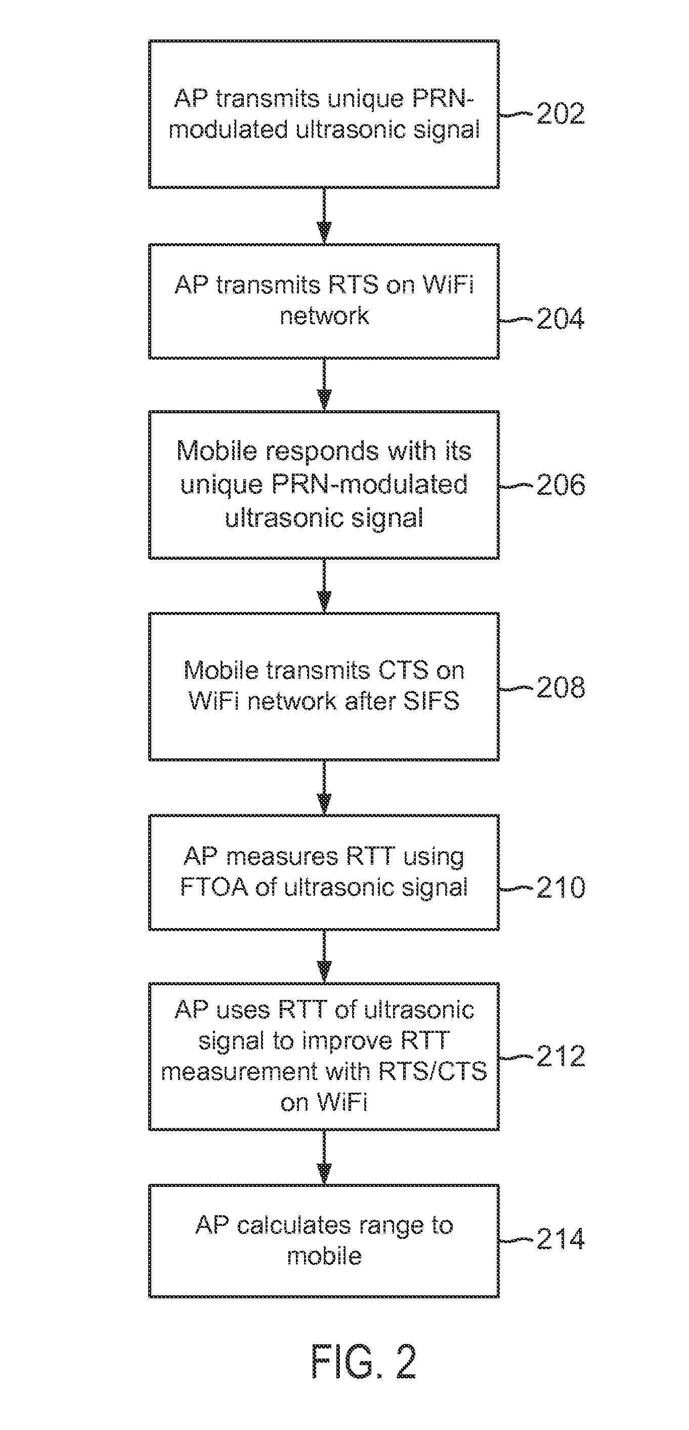
System and methods are disclosed to use ultrasonic (US) and WiFi signals to improve range determination between devices in WiFi-based position or range estimation systems. Such systems may leverage existing WiFi infrastructure and US-capable sensors such as speakers and microphones as US transducers. US ranging between devices may be performed using round-trip time (RTT) or one-way measurements. To enable US ranging between a device and multiple US transmitters simultaneously, the US signal from each US transmitters or from the device may be modulated with a unique pseudo-random number (PRN) using direct sequence spread spectrum (DSSS). The transmission of US signals may be synchronized with the transmission of WiFi beacons which may contain data fields that contain the PRN sequence used to modulate the synchronous US signal. In RTT ranging, a receiving device receiving an US signal transmission may respond with its own PRN-modulated US signal synchronized to its WiFi beacon.

Description

BACKGROUND[0001]This application generally relates to communication systems. In particular, this application relates to methods and systems for estimating the range to, or the position of, a WiFi-enabled communication device.[0002]Many services and applications require knowledge of a position of mobile devices such as smartphones. While GPS receivers have been fairly successful in providing a low-cost solution for position determination, GPS receivers suffer from drawbacks such as severe attenuation of satellite GPS signals when the receivers are operated indoor. With the prevalence of WiFi networks, WiFi signals have increasingly been used to provide positional information of WiFi-enabled devices. WiFi signals have also been used to estimate range between WiFi devices, for example, in gaming applications to determine a distance between a game controller and a console.[0003]In conventional WiFi-based position or range estimation systems, a mobile device may measure the strength of r...

Claims


Application Information

Patent Timeline
Patent Type & Authority Applications(United States)
IPC IPC(8): G01S5/02
CPCG01S2205/008G01S5/02G01S5/14G01S5/30G01S11/16G01S15/74G01S13/878
Inventor BEAUREGARD, STEPHEN J.
Owner QUALCOMM INC
Learn More