Chuck, a Chuck Control System, a Lithography Apparatus and a Method of Using a Chuck

a control system and chuck technology, applied in the direction of instruments, printers, speech analysis, etc., can solve the problems of resistive heating of the chuck, inability to compensate for sudden changes in the dissipation power, and the interior walls of the channel,

Active Publication Date: 2014-09-11
ASML NETHERLANDS BV
View PDF3 Cites 69 Cited by
  • Summary
  • Abstract
  • Description
  • Claims
  • Application Information

AI Technical Summary

Benefits of technology

[0012]It is desirable to at least partially address one or more of the abovementioned problems. For example, it is desirable to provide an arrangement in which the channels and / or external apparatus that is in contact with the fluid do not degrade over time. For example, it is desirable to avoid changes in temperature of the chuck during unmounting and mounting of the patterning device or substrate.

Problems solved by technology

It has been found in such arrangements that the interior walls of the channels, and / or of apparatus external to the chuck that is in contact with the fluid, can degrade over time.
It has also been found that electric current formed within the chuck during operation can lead to resistive heating of the chuck.
However, it can be difficult to compensate for sudden changes in the dissipated power, for example when the chuck is turned off to unmount a patterning device or substrate.

Method used


Image

  • Chuck, a Chuck Control System, a Lithography Apparatus and a Method of Using a Chuck
  • Chuck, a Chuck Control System, a Lithography Apparatus and a Method of Using a Chuck
  • Chuck, a Chuck Control System, a Lithography Apparatus and a Method of Using a Chuck

Examples


Embodiment Construction

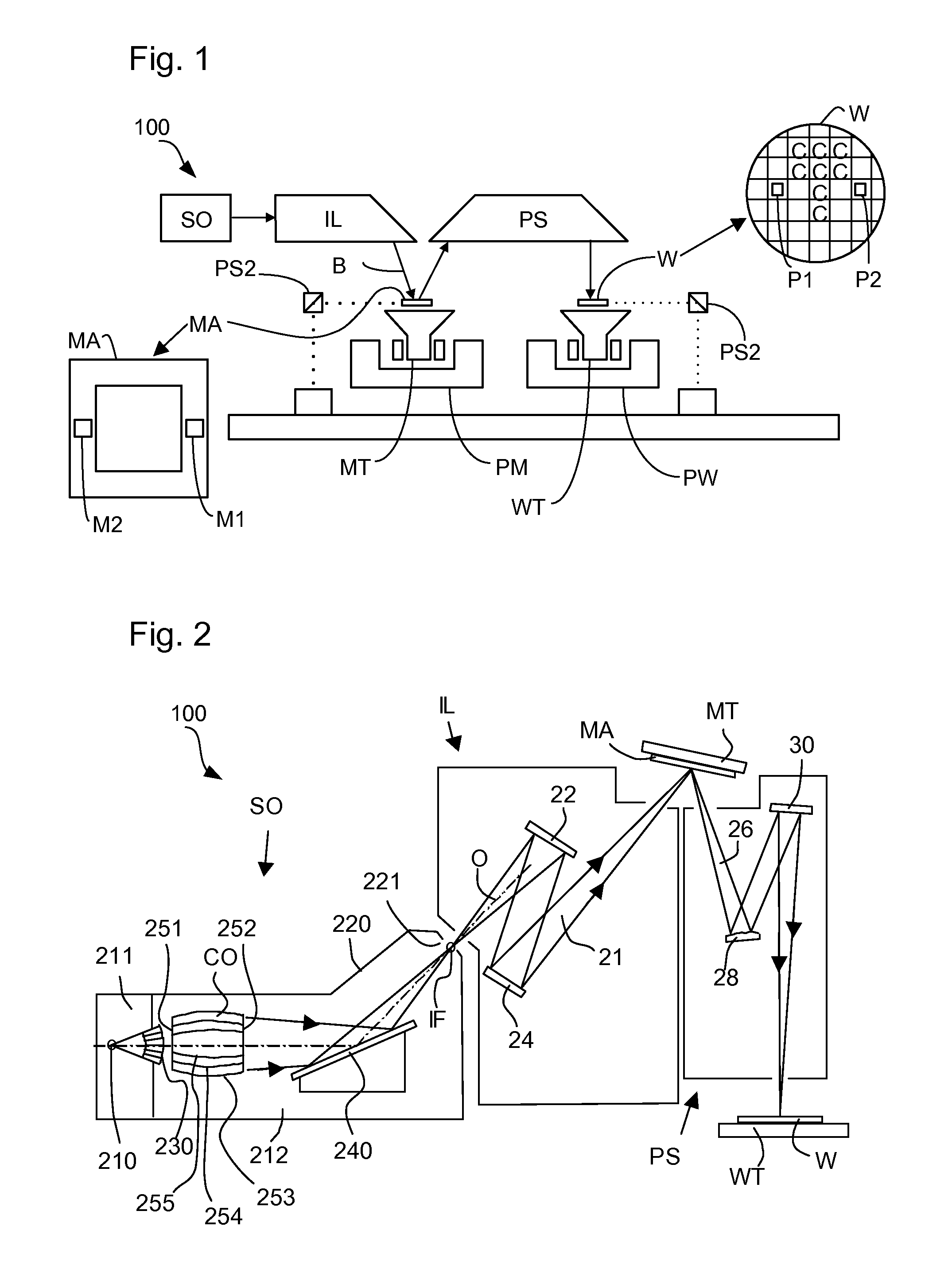
[0026]FIG. 1 schematically depicts a lithographic apparatus 100 including a source collector module SO according to one embodiment of the invention. The apparatus comprises:[0027]an illumination system (illuminator) IL configured to condition a radiation beam B (e.g., EUV radiation).[0028]a support structure (e.g., a mask table) MT constructed to support a patterning device (e.g., a mask or a reticle) MA and connected to a first positioner PM configured to accurately position the patterning device;[0029]a substrate table (e.g., a wafer table) WT constructed to hold a substrate (e.g., a resist-coated wafer) W and connected to a second positioner PW configured to accurately position the substrate; and[0030]a projection system (e.g., a reflective projection system) PS configured to project a pattern imparted to the radiation beam B by patterning device MA onto a target portion C (e.g., comprising one or more dies) of the substrate W.

[0031]The illumination system may include various typ...


PUM

PropertyMeasurementUnit
wavelengthaaaaaaaaaa

Abstract

A chuck, chuck control system, lithographic apparatus and method of using a chuck are disclosed. In an embodiment, there is provided a chuck (43) for use in holding a patterning device (MA) or a substrate (W) onto a supporting table (MT, WT) of a lithography apparatus (100) by electrostatic force, in which the patterning device is for imparting a radiation beam (B) with a pattern in its cross-section to form a patterned radiation beam, and the substrate is for receiving the patterned radiation beam; said chuck comprising: a dielectric member (45); a temperature conditioning fluid channel (48) formed within the chuck; a drive electrode (40,42) for applying a potential difference between the drive electrode and the patterning device or substrate across the dielectric member in order to electrostatically attract the patterning device or substrate towards the drive electrode; and a first shield electrode (60) for reducing or preventing the development of an electric field across temperature conditioning fluid in the temperature conditioning fluid channel due to a voltage applied to the drive electrode, in order to reduce or prevent electrolysis in the fluid.

Description

CROSS-REFERENCE TO RELATED APPLICATIONS[0001]This application claims the benefit of U.S. provisional application 61 / 544,039, which was filed on 6 Oct. 2011, and which is incorporated herein in its entirety by reference.FIELD[0002]The present invention relates to a chuck, a chuck control system, a lithographic apparatus and a method of using a chuck.BACKGROUND[0003]A lithographic apparatus is a machine that applies a desired pattern onto a substrate, usually onto a target portion of the substrate. A lithographic apparatus can be used, for example, in the manufacture of integrated circuits (ICs). In that instance, a patterning device, which is alternatively referred to as a mask or a reticle, may be used to generate a circuit pattern to be formed on an individual layer of the IC. This pattern can be transferred onto a target portion (e.g., comprising part of, one, or several dies) on a substrate (e.g., a silicon wafer). Transfer of the pattern is typically via imaging onto a layer of ...

Claims


Application Information

Patent Timeline
Patent Type & Authority Applications(United States)
IPC IPC(8): G03F7/20H01L21/683
CPCH01L21/6831G03F7/70708G03F7/70875G10L15/08G10L2015/223G03F7/707G03F7/70908
Inventor CORNELISSEN, SEBASTIAAN MARIA JOHANNESGILISSEN, NOUD JANSIJBEN, ANKO JOZEF CORNELUSSCHMITZ, ROGER WILHELMUS ANTONIUS HENRICUSNOTENBOOM, ARNOUD WILLEMVAN DER WILK, RONALDWILL, MANON ELISE
Owner ASML NETHERLANDS BV
Why Eureka
Try Eureka