Three-level converter

a converter and three-level technology, applied in the field of converters, can solve the problems of large volume high cost and failure rate, etc., and achieve the effect of reducing stray inductance, facilitating installation and replacement procedures, and substantial technical improvements

Active Publication Date: 2014-09-11
DELTA ELECTRONICS INC
View PDF33 Cites 34 Cited by
  • Summary
  • Abstract
  • Description
  • Claims
  • Application Information

AI Technical Summary

Benefits of technology

[0010]In view of the foregoing, one purpose of the present disclosure is to provide a layout design of a three-level converter. The layout uses a modulized design. The product is compact in structure and easy for installation and maintenance. Also, the commutation loop of the converter is small, and the stray inductance is also small. Further, the manufacturing cost of such products is low. Accordingly, the solution provided herein effectively addresses the problems in the prior art.
[0023]In view of the foregoing, the technical solutions of the present disclosure result in significant advantageous and beneficial effects, compared with existing techniques. The implementation of the above-mentioned technical solutions achieves substantial technical improvements and provides utility that is widely applicable in the industry. Specifically, technical advantages generally attained, by embodiments of the present disclosure, include:
[0024]1. The proposed modulized design uses half of the bridge arm as a module; thereby facilitating the installation and replacement procedures and resulting in a compact structure with a smaller commutation loop and reduced stray inductance;
[0025]2. The connecting elements are composed of a combination of connecting busbars (i.e., those made of conductive materials; such as copper busbar or aluminum) and insulated wires (i.e., insulated cables), as compared with other products in which all the connecting elements are busbars; in this way, the present disclosure effectively avoid the problem of local discharge (or partial discharge) resulted from the high-voltage during the connecting process of the system; and
[0026]3. The upper-half bridge arm circuit and the lower-half bridge arm circuit are disposed side by side and facing each other; this feature, in combination with the features (1) and (2) identified above, results in a converter with a smaller commutation loop, a reduced stray inductance and a compact structure; also, the converter is easy to install and the manufacturing cost of such converter is low.

Problems solved by technology

However, the frequency converter according to the ROBICON solution requires a phase-shifting transformer disposed in the front, and hence, the transformer is costly and bulky and associated with more energy loss.
Further, the ROBICON solution requires a large number of capacitors, resulting in higher cost and failure rate.
In view of the foregoing, the solution is massive in volume, low in efficiency and inferior in reliability.
Other high voltage frequency converter products use a high-voltage semiconductor component to achieve the high voltage frequency conversion, yet the high-voltage semiconductor is very expensive and associated with higher energy loss, and hence the cost of the system is high.
However, the design layout of such products is defective due to the inferior maintainability, large commutation loop and high manufacturing cost.
In view of the foregoing, there exist problems and disadvantages in the current technology and further improvements are required for those ordinarily skilled in the art to solve the above-mentioned problems.
Further, the manufacturing cost of such products is low.

Method used


Image

  • Three-level converter
  • Three-level converter
  • Three-level converter

Examples


first embodiment

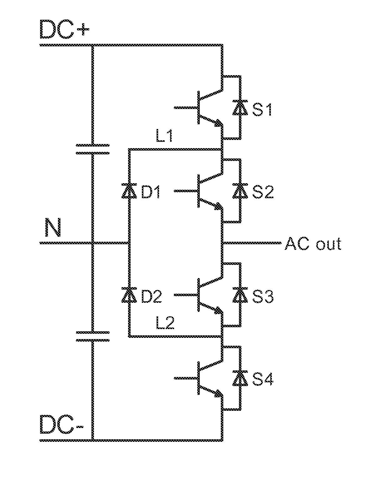
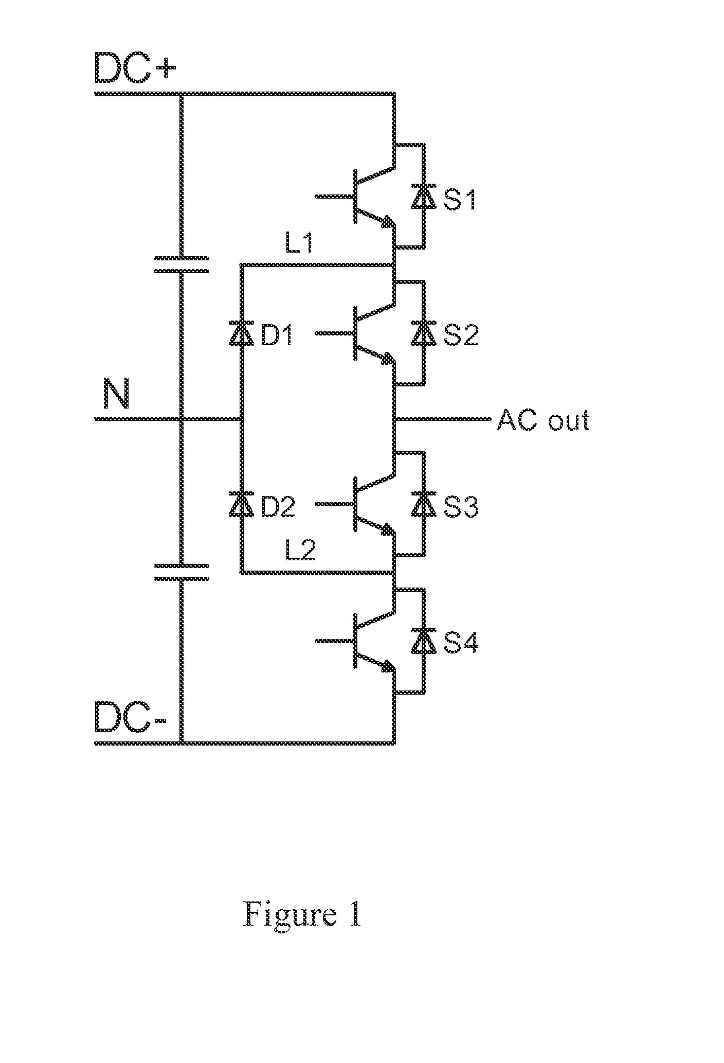
[0045]In the first embodiment, the structural design of the overall bridge arm is illustrated in FIG. 10, in which the structure of the upper-half bridge arm is depicted in FIG. 6 and FIG. 7, and the upper-half bridge arm circuit module comprises a first switch unit (S1), a second switch unit (S2) and a first diode unit (D1). The structure of the lower-half bridge arm is depicted in FIG. 8 and FIG. 9, and the lower-half bridge arm circuit module comprises a third switch unit (S3), a fourth switch unit (S4) and a second diode unit (D2).

[0046]In structural design, the switch unit (S1) is disposed at the upper portion of the upper-half bridge arm, the diode unit (D1) is disposed at the middle portion of the upper-half bridge arm, whereas the switch unit (S2) is disposed at the lower portion of the upper-half bridge arm; the switch unit (S3) is disposed correspondingly to the position of S2 and is located at the lower portion of the lower-half bridge arm, the diode unit (D2) is disposed...

second embodiment

[0048]the present disclosure is illustrated in FIGS. 11, 12 and 13. FIG. 11 illustrates the circuit structure layout of an upper-half bridge arm of a three-level single-phase bridge arm. As illustrated in FIG. 11, the first switch unit (S1) and the second switch unit (S2) are vertically disposed with the first switch unit (S1) being at the top while the second switch unit (S2) being at the bottom, and the first diode unit (D1) is disposed by the side of the first switch unit (S1) and the second switch unit (S2), thereby giving an overall arrangement in a delta (A) shape. FIG. 12 illustrates the circuit structure layout of a lower-half bridge arm of a three-level single-phase bridge arm. As illustrated in FIG. 12, the overall structure is also arranged in a delta (A) shape, in which the third switch unit (S3) is disposed at the bottom, the fourth switch unit (S4) is disposed at the top, and the second diode unit (D2) is disposed by the side of the third switch unit and fourth switch ...


PUM


Abstract

A three-level converter includes at least one phase bridge arm, each including an upper-half and a lower-half bridge arm circuit modules. The upper-half bridge arm circuit module includes a first and a second switch units that are in series connection, and a first diode unit. The lower-half bridge arm circuit module includes a third and a fourth switch units that are in series connection, and a second diode unit. The first and second diode units are connected to the neutral point of the capacitor unit; the second and third switch units are connected to the alternating-current terminal; The first and the fourth switch unit is respectively connected to the positive terminal and negative terminal of the direct-current bus; the capacitor unit is connected to the direct-current bus between the positive and negative terminals. The two modules are disposed side by side and facing each other.

Description

RELATED APPLICATIONS[0001]This application claims priority to Chinese Application Serial Number 201310074909.7, filed on Mar. 8, 2013, the entirety of which is herein incorporated by reference.BACKGROUND[0002]1. Technical Field[0003]The present disclosure relates to a converter, and more particularly, a three-level converter.[0004]2. Description of Related Art[0005]Frequency converter has wide applications in industrial control, and is particularly important in the control and speed regulation of high-power electrical machines. Therefore, the converter is an important part of the energy system. In the industrial applications, the high power or medium power high voltage electrical machines play more and more important roles, which consume about two-thirds of the gross power generation. Accordingly, it is significant to improve the efficiency of these machines.[0006]The existing ROBICON solution (U.S. Pat. No. 5,625,545) employs a frequency converter in which the high-voltage frequenc...

Claims


Application Information

Patent Timeline
Patent Type & Authority Applications(United States)
IPC IPC(8): H02M7/5387
CPCH02M7/5387H02M7/003H02M7/487H02M1/088
Inventor YING, JIAN-PINGMA, SHAO-CAIGAN, HONG-JIANWEN, SEN-LIN
Owner DELTA ELECTRONICS INC
Why Eureka
Try Eureka