
Method for measuring position of user terminal

a user terminal and position measurement technology, applied in the direction of measuring devices, instruments, electrical appliances, etc., can solve the problems of unfavorable system complexity, measurement error, wave propagation speed, etc., and achieve the effect of reducing position measurement error, simplifying the position measurement process, and raising accuracy of position measuremen

Inactive Publication Date: 2014-09-11
INTELLECTUAL DISCOVERY CO LTD
View PDF5 Cites 8 Cited by
  • Summary
  • Abstract
  • Description
  • Claims
  • Application Information

AI Technical Summary

Benefits of technology

The present invention improves position measurement accuracy by using a neighboring terminal as a relay terminal to act as an anchor node. This simplifies the position measurement process and reduces errors. Additionally, securing a LOS with a neighboring terminal further improves accuracy.

Problems solved by technology

Factors affecting the measurement error ni include variation in wave propagation speed caused by an unstable atmospheric state, thermal noise of a reception circuit, diffraction, scattering, etc.
However, this method is very unfavorable in terms of system complexity.
In addition, although an attempt to reduce errors using additional information such as angle of arrival has been made in “An Efficient Geometry-Constrained Location Estimation Algorithm for NLOS Environments”, this method has constraints in that an anchor node should have multiple antennas.
However, the anchor node consumes substantial installation costs because it is equipment such as a satellite or a cellular base station.
In addition, the anchor node is disadvantageous in that it is impossible to flexibly cope with variable demand.

Method used


Image

  • Method for measuring position of user terminal
  • Method for measuring position of user terminal
  • Method for measuring position of user terminal

Examples


Embodiment Construction

[0027]The above and other objects, features and advantages of the present invention will be more clearly understood from the following detailed description taken in conjunction with the accompanying drawings and those skilled in the art will be able to easily implement the technical sprits of the present invention. In describing the present invention, when it is determined that the detailed description of the known art related to the present invention may obscure the gist of the present invention, the detailed description thereof will be omitted. Reference will now be made in detail to the preferred embodiments of the present invention, examples of which are illustrated in the accompanying drawings. The same reference numbers will be used to refer to the same or like parts.

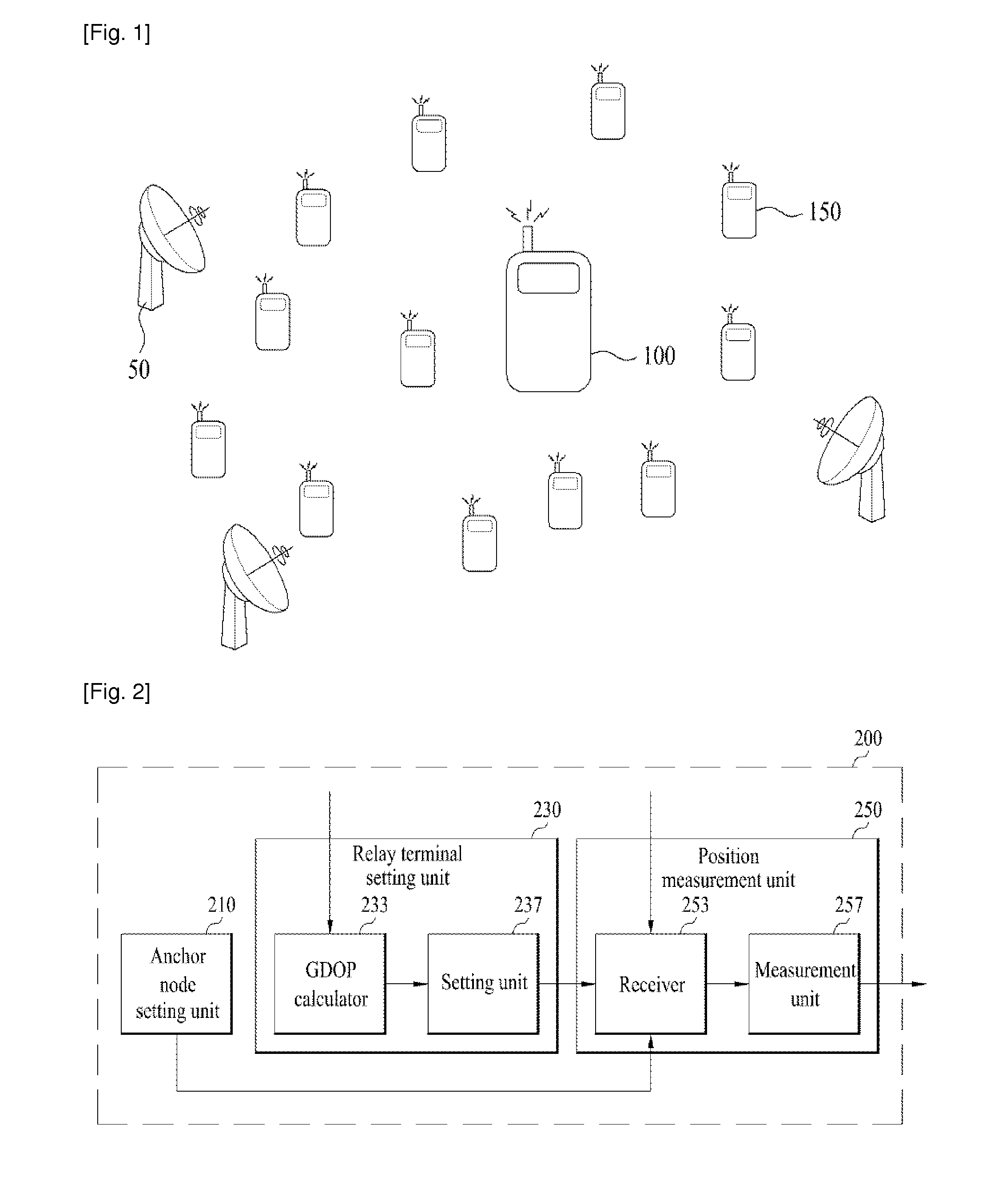
[0028]FIG. 1 is a diagram illustrating a system environment according to an exemplary embodiment of the present invention.

[0029]Triangulation may be used for position determination. In a system environment accordi...


PUM


Abstract

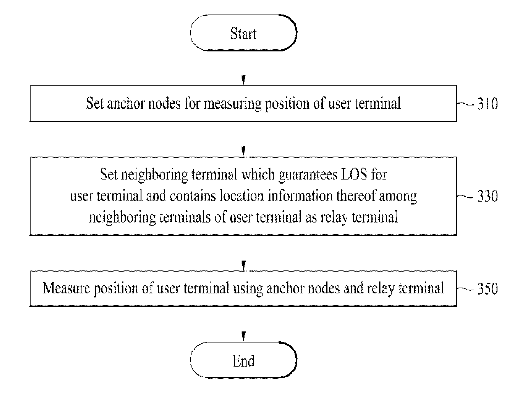
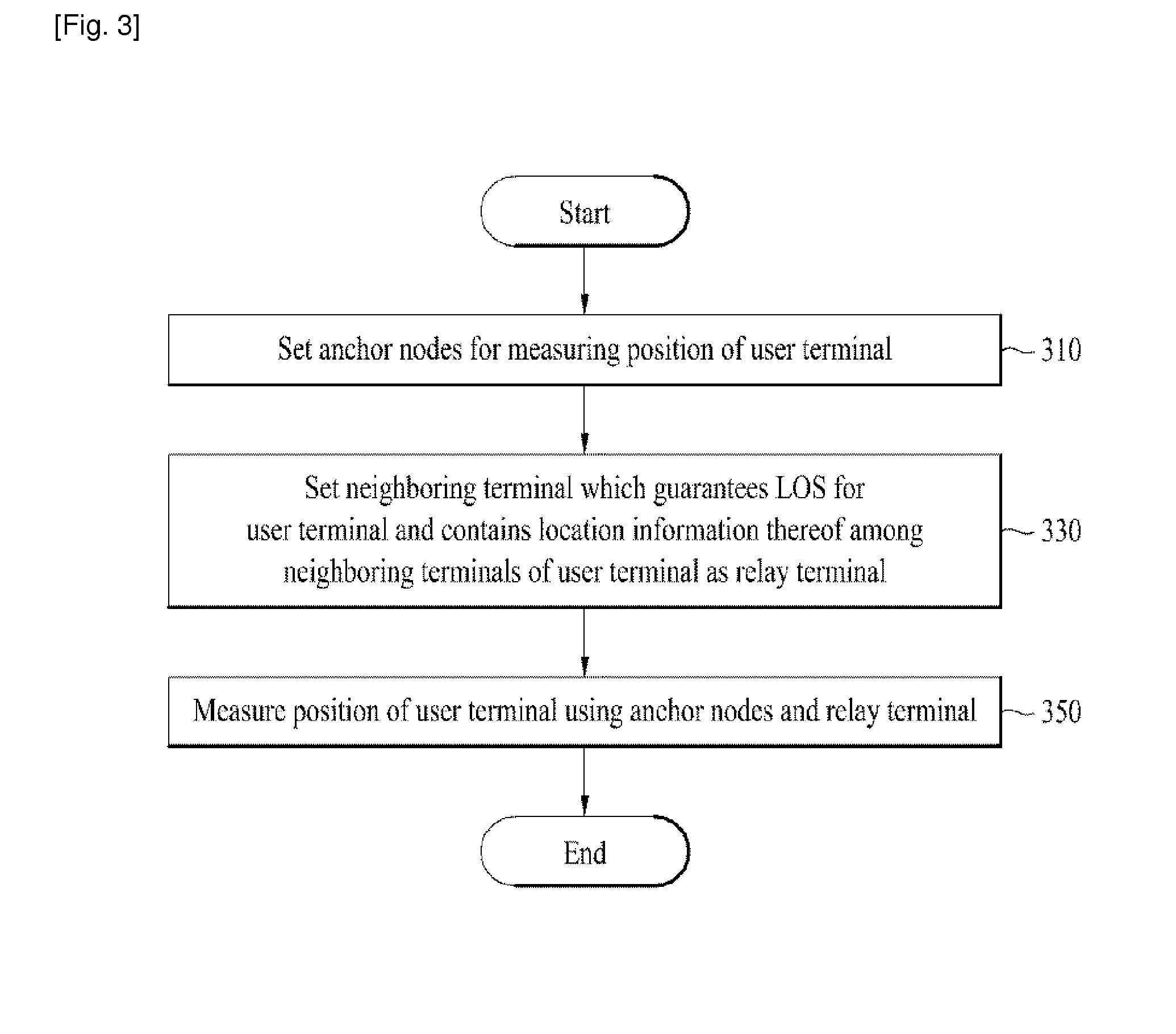
A method for measuring a position of a user terminal is provided. The method includes selecting one or more anchor nodes for measuring the position of the user terminal, selecting a relay terminal from neighboring terminals of the user terminal, each of the neighboring terminals securing a Line Of Sight (LOS) with the user terminal and having location information thereof, and measuring the position of the user terminal using the one or more anchor nodes and the relay terminal.

Description

TECHNICAL FIELD[0001]The present invention relates to a method for measuring the position of a user terminal, and more particularly, to a method for measuring the position of a user terminal using a relay terminal.BACKGROUND ART[0002]A typical radio positioning technique includes a scheme using a Global Positioning System (GPS), a Time Of Arrival (TOA) scheme using an arrival time of electro-magnetic waves, which is a principle of position recognition, a scheme using infrared rays, ultrasonic waves, and Radio Frequency (RF), and a scheme using Radio Frequency Identification (RFID).[0003]Among these schemes, the positioning technique based on the TOA of electro-magnetic waves performs position measurement as followings. Firstly, a transmitter transmits a signal conveys a timestamp which issued by the transmitter. After that a receiver estimates the distance between the transmitter and the receiver by comparing a signal reception time with a signal transmission time recorded on the ti...

Claims


Application Information

Patent Timeline
Patent Type & Authority Applications(United States)
IPC IPC(8): G01S5/04H04W24/00
CPCH04W24/00G01S5/04G01S5/0226G01S5/145
Inventor KIM, YOUNG JUNKO, YOUNG CHAL
Owner INTELLECTUAL DISCOVERY CO LTD
Learn More