This helps you quickly interpret patents by identifying the three key elements:
Problems solved by technology
Method used
Benefits of technology
Benefits of technology
The present invention provides a bonding system that can easily and uniformly heat an electronic component from one side. The system uses a tool base and laser beam to heat the electronic component. The laser power is set higher for the four corner parts of the electronic component, which tend to dissipate more heat. This ensures that the entire target area of the electronic component is heated up evenly. This technical effect makes it easy and efficient to bond electronic components to substrates.
Problems solved by technology
However, since the whole of the one surface of the electronic component is heated, in the case where the peripheral region of the electronic component tends to dissipate more heat than the inner region, it is difficult to uniformly heat the electronic component, and the temperature of the peripheral region of the electronic component is lower than that of the inner region.
However, both surfaces of the electronic component have to be irradiated with a laser beam, so that the electronic component cannot be heated in a state where the electronic component is pressed against the substrate.
However, the configuration of the bonding system according to Patent Literature 2 is not suitable for heating the four corner parts to a higher temperature than the other parts.
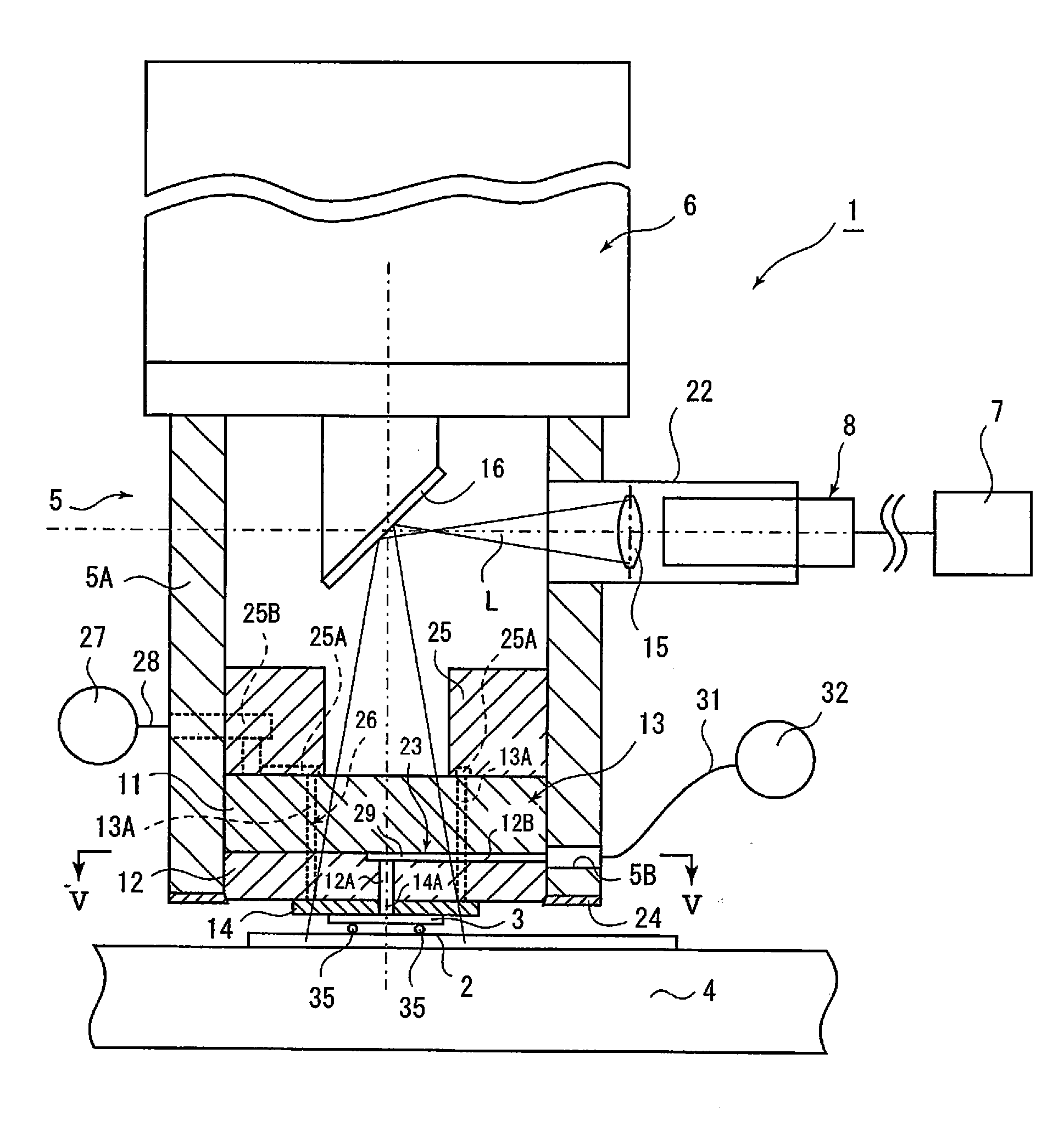
Furthermore, an optical fiber 8 needs to be vertically displaced to change the point of application of the laser beam, and therefore, adjustments take a long time each time an IC chip 1 having a different thickness or made of a different material is placed in the bonding system.
Method used
Image
Click on the blue label to locate the original text in one second.
Reading with bidirectional positioning of images and text.
Examples
second embodiment
[0067]FIG. 6 is a diagram for illustrating the present invention. According to the second embodiment, the heating region S is divided into four types of sub-regions.
[0068]Specifically, according to this embodiment, the heating region S is divided into four corner sub-regions S1, corner-adjoining sub-regions S4 surrounding the corner sub-regions S1, outer sub-regions S3 that are the outer peripheral sub-regions forming the outer peripheral edges of the electronic component 3 excluding the corner sub-regions S1 and the corner-adjoining sub-regions S4, and the inner sub-region S2 described above.
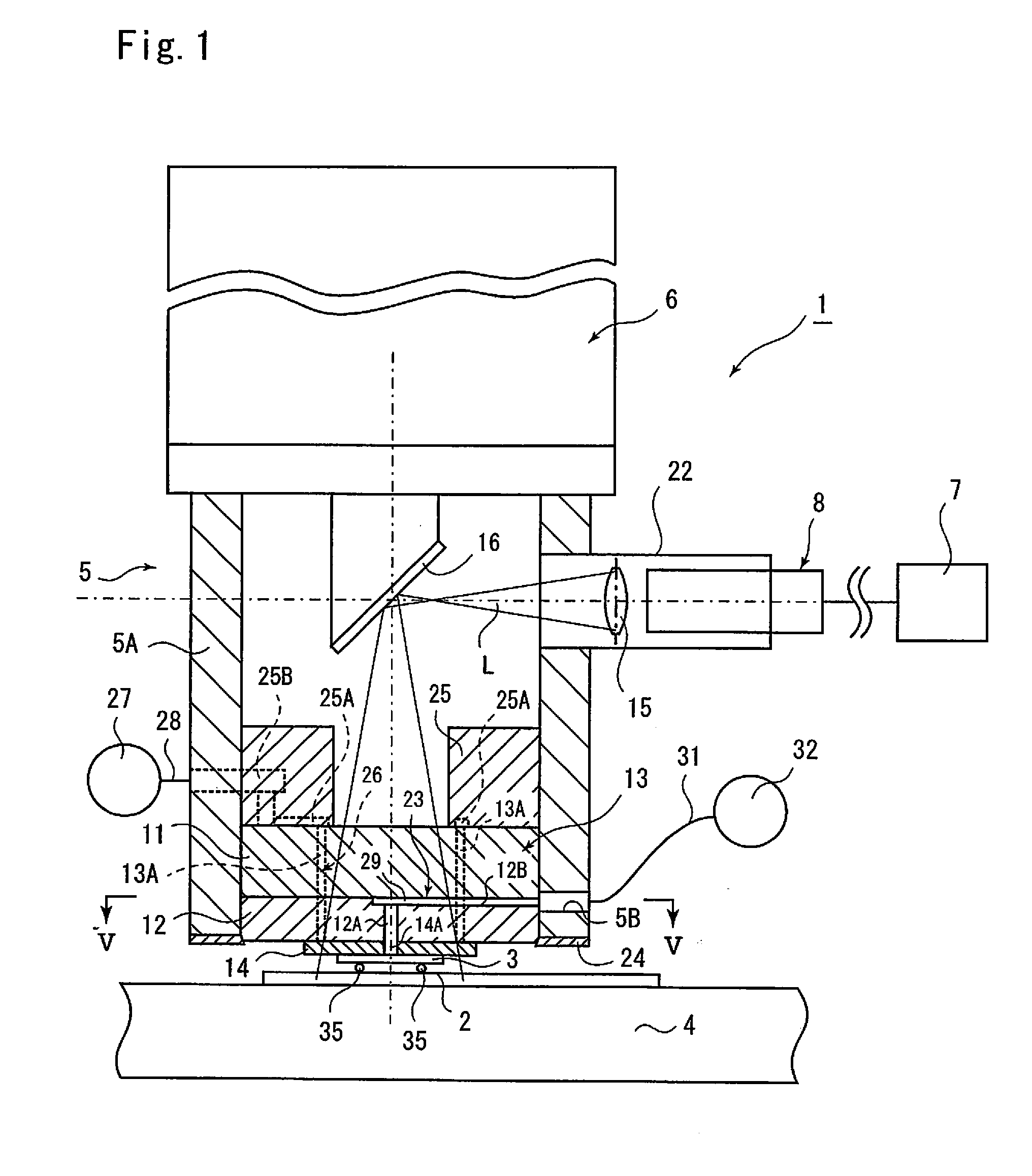
[0069]In this embodiment, the 36 optical fibers f1 to f36 are bundled in a line, and the laser beam inlets of the optical fibers f1 to f36 are connected to separate laser resonators 7-1 to 7-36 as shown in FIG. 7. That is, each optical fiber is connected to a different laser resonator, and the laser power of each laser resonator can be independently controlled.
[0070]As shown in FIG. 6, of the f...
first embodiment
[0075]The inner sub-region S2 in this embodiment faces a total of twelve optical fibers f9, f10, f14, f15, f16, f17, f20, f21, f22, f23, f27 and f28. In this embodiment, as in the first embodiment, the non-irradiation sub-region S2′ is provided at the center of the inner sub-region S2, and four optical fibers f15, f16, f21 and f22 face the non-irradiation sub-region S2′.
[0076]Therefore, four laser resonators 7-15, 7-16, 7-21 and 7-22 connected to the four optical fibers f15, f16, f21 and f22 facing the non-irradiation sub-region S2′ are not activated to oscillate a laser beam. If the bonding system 1 is dedicated for the electronic component 3, of course, the four laser resonators 7-15, 7-16, 7-21 and 7-22 can be omitted.
[0077]The eight laser resonators 7-9, 7-10, 7-14, 7-17, 7-20, 7-23, 7-27 and 7-28 connected to a total of eight optical fibers f9, f10, f14, f17, f20, f23, f27 and f28 facing the inner sub-region S2 excluding the non-irradiation sub-region S2′ are set at the fourth ...
PUM
Property
Measurement
Unit
Power
aaaaa
aaaaa
Abstract
A bonding system 1 includes a plurality of laser resonators 7 and a plurality of optical fibers f1 to f36 each having a laser beam inlet connected to one of the plurality of laser resonators. The optical fibers are bundled, and laser beam outlets of the optical fibers are disposed so as to optically face a heating region S of an electronic component 3, and the heating region is irradiated with spots of laser beams emitted from the laser beam outlets. The heating region S is divided into at least corner sub-regions S1 at the corners of the electronic component and an inner sub-region S2 inside the electronic component, and the laser power of the laser resonators whose laser beam outlets face the corner sub-regions is set higher than the laser power of the laser resonators whose laser beam outlets face the inner sub-region.For example, in the case where the electronic component has a rectangular shape, the four corner sub-regions S1, which tend to dissipate more heat, can be heated with higher laser power, so that the electronic component can be uniformly heated.
Description
FIELD OF THE INVENTION [0001]The present invention relates to a bonding system that bonds an electronic component to a substrate. In particular, the present invention relates to a bonding system suitable for bonding an electronic component having a polygonal shape to a substrate by heating the electronic component with a laser beam.DESCRIPTION OF THE PRIOR ART [0002]There is a known conventional bonding system that comprises a laser resonator that oscillates a laser beam, light guide means that guides the laser beam oscillated by the laser resonator and a tool base through which the laser beam guided by the light guide means is transmitted and bonds an electronic component having a polygonal shape to a substrate by heating the electronic component with the laser beam transmitted through the tool base (Patent Literature 1: Japanese Patent Laid-Open No. 2010-129890).[0003]There is another conventional bonding system that can uniformly heat the whole of an electronic component by apply...
Claims
Application Information
Patent Timeline
Application Date:The date an application was filed.
Publication Date:The date a patent or application was officially published.
First Publication Date:The earliest publication date of a patent with the same application number.
Issue Date:Publication date of the patent grant document.
PCT Entry Date:The Entry date of PCT National Phase.
Estimated Expiry Date:The statutory expiry date of a patent right according to the Patent Law, and it is the longest term of protection that the patent right can achieve without the termination of the patent right due to other reasons(Term extension factor has been taken into account ).
Invalid Date:Actual expiry date is based on effective date or publication date of legal transaction data of invalid patent.
