Mooring system with decoupled mooring lines and/or riser system

a mooring line and riser technology, applied in the field of vessels, can solve the problems of inability to change out offshore, the turret system cannot function anymore as a weathervaning system, and the large disconnectable turret is not suitable for large disconnectable turrets, so as to reduce the snatch load in the pull-in line and the effect of reducing the snatch load

Active Publication Date: 2014-09-18
SINGLE BUOY MOORINGS INC
View PDF1 Cites 5 Cited by
  • Summary
  • Abstract
  • Description
  • Claims
  • Application Information

AI Technical Summary

Benefits of technology

[0015]Because the maximum tension in the pull-in line is no longer influenced by the mass and added mass of the buoyant body, which is frequency dependent, large dynamic loads in the pull-in line are avoided. Therefore, the size of the buoyant body can be increased without restrictions in order to accommodate larger riser systems in case the system is pulled in through the mooring line fairleads on the buoy or to accommodate larger mooring systems in case the system is pulled in through the riser porches on the buoy.
[0028]In order to prevent the pull-in line from damaging the top of the buoy when the pull-in line goes slack upon connection and / or disconnection of the buoy to the cavity, the pull-in line may near a top part of the buoyant body be provided with a flexible sheath. In case the pull-in line is formed by a chain, the sheath may be in the form of a flexible hose slightly larger than the chain width to keep the chain at a distance from the buoy when the pull-in line goes slack.

Problems solved by technology

A disadvantage of this combined and interconnected roller ball bearing assembly is that if one or more roller balls fails, the complete assemble has to be changed out, meaning that the turret system cannot function anymore as a weathervaning system.
This change out cannot be done offshore.
The known combined roller bearing system, due to the fabrication limitations, is limited to about only 8 meters, so that it not suitable for large disconnectable turret-buoy systems with for example 20 or more risers connected to the buoy.
This system is therefore not advantageous for disconnectable turret-buoys systems sized to receive numerous of risers, and of course is not possible when using only hard piping.
Further, as the mooring legs are directly connected to the turret, the riser buoy has only sufficient buoyancy to support the risers.
The known mooring system does not function as a quick disconnectable system that is suitable to be used in cyclone areas or ice infested waters as the mooring legs stays connected to the turret.
Also hook-up of both the riser supporting buoy and the weight together is only possible for relatively small buoys and weights and not for large buoys with large connected weights, as this would require a winch capacity exceeding the capacity of winches available in the field and involving the danger of creating large snap-loads in the hauling-in line that connects the buoy and the winch.
This results in large winches that are designed to withstand such snatch loads.
In these known systems the capability to reconnect a buoy to a turret is mainly limited by the sea state and winch capacity.
If the sea states are too large, snatch loads and buoy acceleration forces are exerted on the connection lines that exceed the strength of available reconnection lines.

Method used


Image

  • Mooring system with decoupled mooring lines and/or riser system
  • Mooring system with decoupled mooring lines and/or riser system
  • Mooring system with decoupled mooring lines and/or riser system

Examples


Embodiment Construction

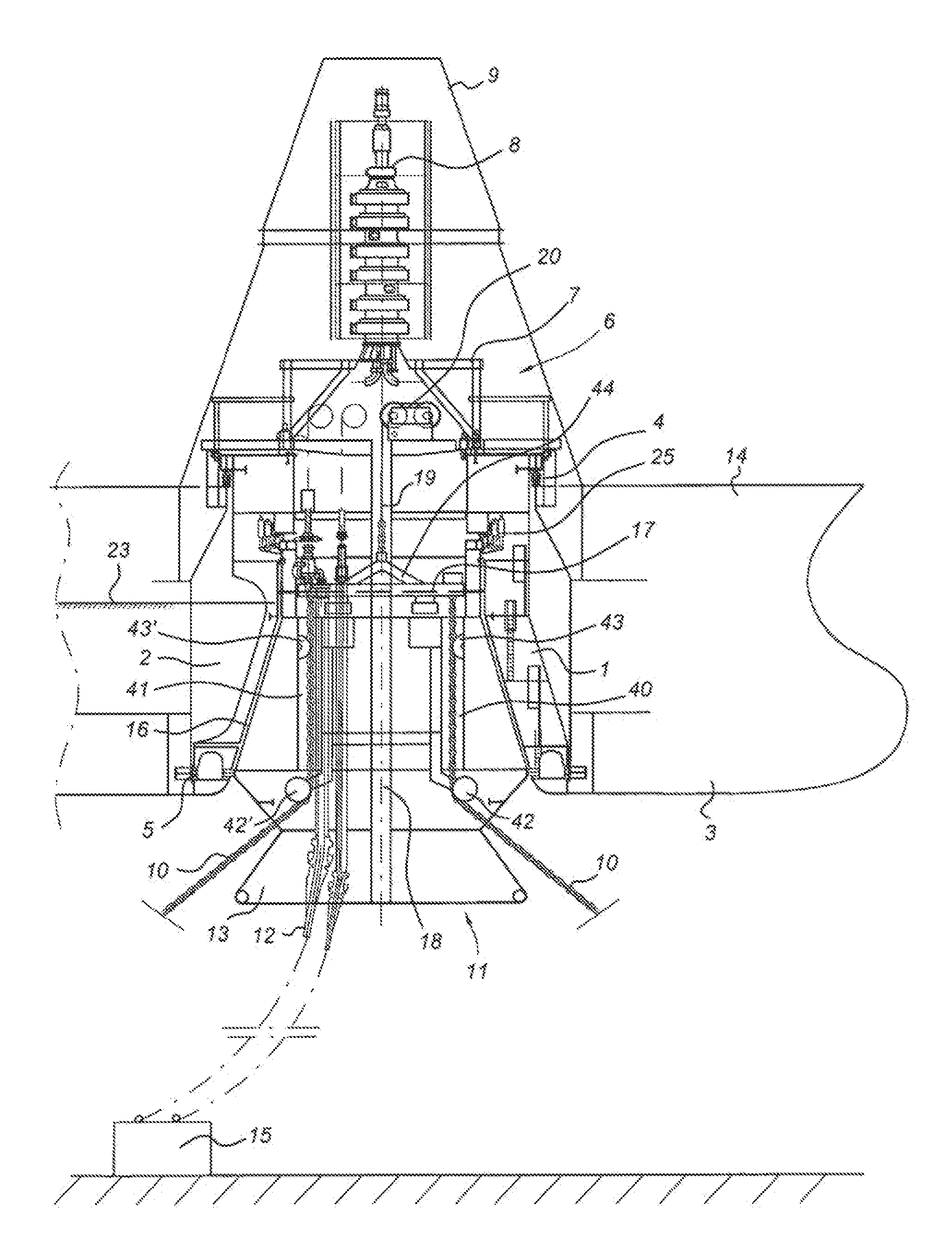
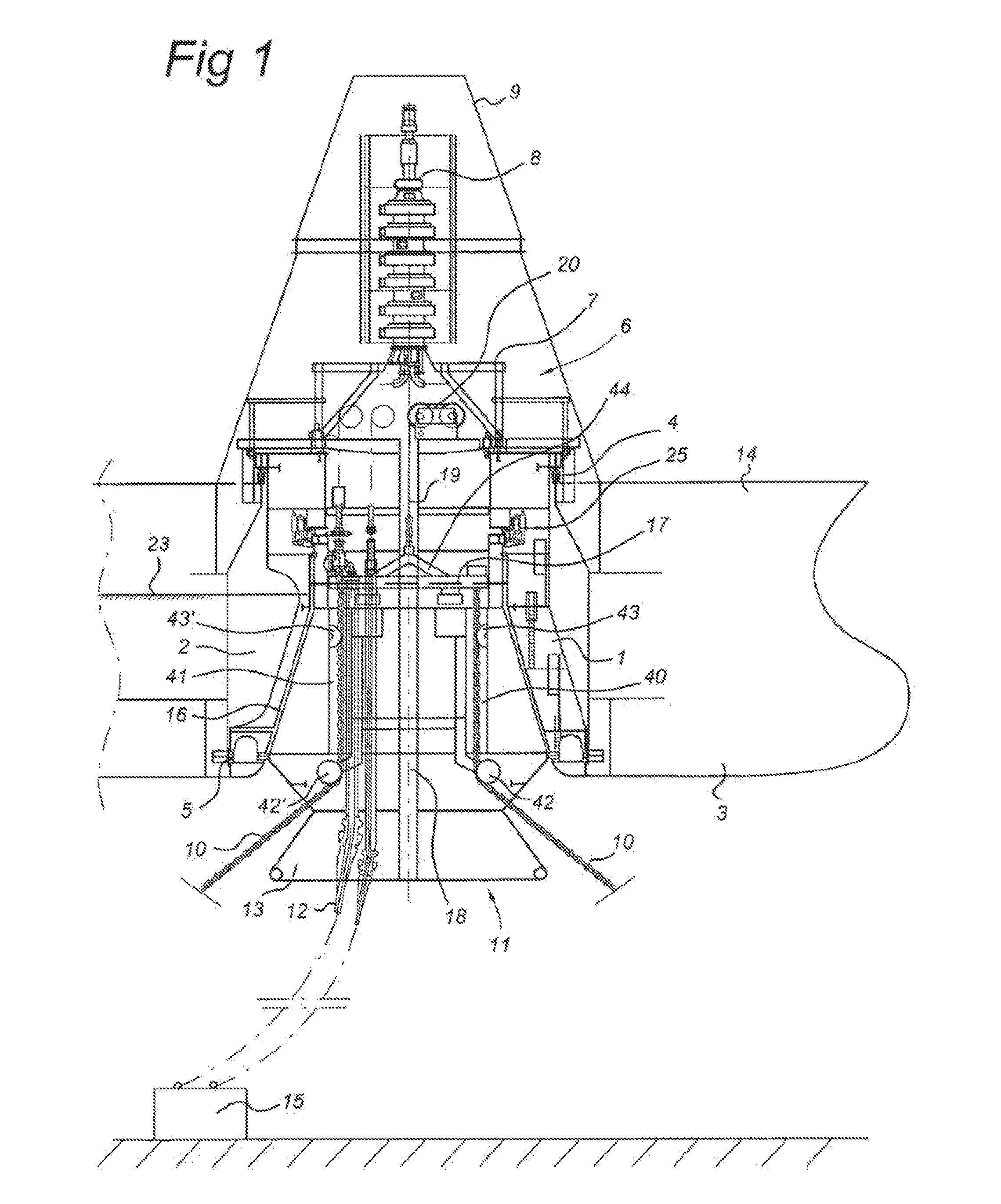
[0036]FIG. 1 shows a sectional view of a disconnectable turret mooring system according to the present invention.

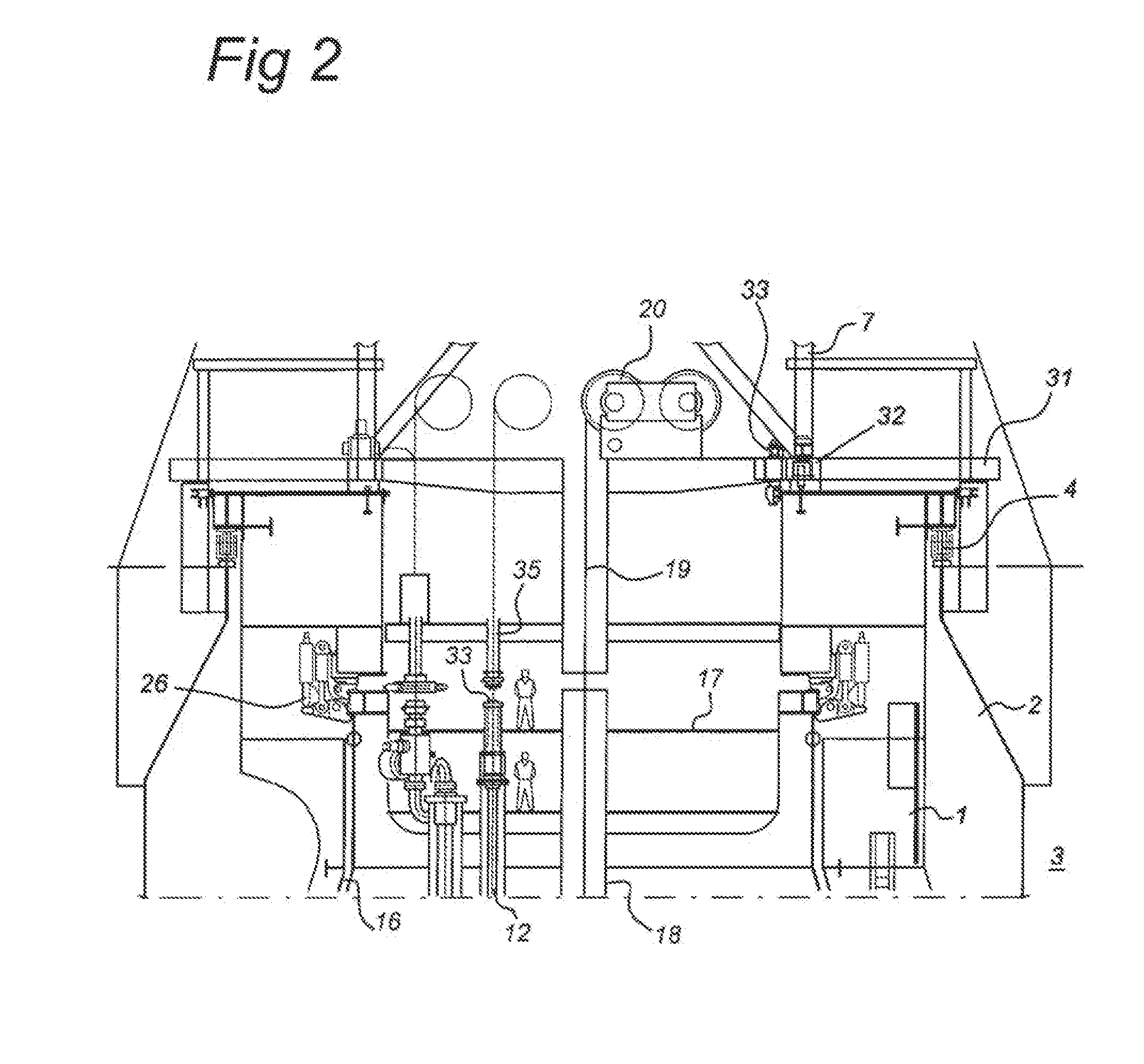
[0037]The system consists of a cylindrical turret structure 1 located within a cylindrical moonpool 2 integrated into the hull 3 of a vessel 14, which for example could be a FPU or FPSO. The turret bearing system connecting and aligning the turret to the moonpool of the vessel consists of a large diameter top bogie bearing 4 and (optionally) a bottom low friction pad radial bearing system 5.

[0038]A large multi-deck superstructure 6 is located on top of the turret 1 and houses installation and production equipment, piping manifolds 7 and the fluid / gas swivel stack 8 for the incoming production fluids, exported fluids and the control / chemical umbilicals.

[0039]A steel frame is positioned above and around the superstructure. A casing 9, which is connected to the vessel, supports the piping extending from the fluid swivel stack 8 to the FPU, provides access to the turret 1 fro...


PUM


Abstract

A vessel includes a hull with a turret, a cavity in the turret and a mooring buoy releasably attached in the cavity, the buoy including a buoyant body and carrying a number of risers, extending to a subsea hydrocarbon well and a number of anchor lines connected to the sea bed, wherein upon connection of the buoy to the cavity, the buoy is attached to a pulling member connected to a winch on the vessel for lifting of the buoy. Each anchor line and / or riser at its upper end is connected to a stopper member, the stopper member being attached to the pulling member, wherein during lifting, each anchor line and / or riser and the stopper member are movable relative to the buoyant body in a length direction of the anchor lines and / or risers, and wherein after connection of the buoyant body to the cavity, the stopper member is engaged with an abutment member on the buoyant body to support the anchor line and / or riser weight off the body.

Description

FIELD OF THE INVENTION[0001]The invention relates to a vessel comprising a hull having a turret, a cavity in the turret and a mooring buoy releasably attached in the cavity, the buoy comprising a buoyant body and carrying a number of risers extending to a subsea hydrocarbon well and a number of anchor lines connected to the sea bed, wherein upon connection of the buoy to the cavity, the buoy is attached to a pulling member connected to a winch on the vessel for lifting of the buoy.BACKGROUND OF THE INVENTION[0002]Such a disconnectable mooring system is disclosed in U.S. patent application US2007 / 155259. The known system includes a buoy that is provided with a conical outer casing and a corresponding conical cavity or receptacle on the vessel's turret structure, which cavity has a cone shape corresponding to the conical outer casing of the buoy member. The turret structure includes a turntable carrying conduits to be connected to the risers, wherein the turntable is supported on a be...

Claims


Application Information

Patent Timeline
Patent Type & Authority Applications(United States)
IPC IPC(8): B63B21/50B63B22/02
CPCB63B22/02B63B21/507B63B22/026B63B21/508
Inventor LAVAGNA, PHILIPPECONNAULTE, XAVIERVOGT, CHRISTOPH
Owner SINGLE BUOY MOORINGS INC
Why Eureka
Try Eureka