Wear protection features for corona igniter

a technology of wear protection and corona, which is applied in the field of corona igniters, can solve the problems of reducing the quality of corona formation and combustion, not always avoiding arc formation, erosion and/or corrosion etc., and achieves a wider volume of corona discharge and high field strength. , the effect of reducing corrosion and erosion damage to the firing tips of the crown

Active Publication Date: 2014-09-18
FEDERAL MOGUL IGNITION
View PDF33 Cites 5 Cited by
  • Summary
  • Abstract
  • Description
  • Claims
  • Application Information

AI Technical Summary

Benefits of technology

[0011]The corona igniter including the central extended member with the extended length greater than the crown length provides several advantages over comparative corona igniters without the central extended member. When a grounded component, such as the piston, comes close to the central firing end of the central extended member and the firing tips of the crown, if any arc forms it will preferentially form between the piston and central firing end of the central extended member due to the extended length of the central extended member, its proximity to the grounded component, and hence its higher field strength compared to the firing tips of the crown. Therefore, if arcing does occur, corrosion and erosion damage to the firing tips of the crown is reduced.
[0012]Furthermore, in situations where the grounded components are far from the corona igniter, the central extended member tends to repel the corona streamers as they form, thereby providing a wider volume of corona discharge and reducing the tendency of the corona discharge to approach the piston and form an arc.

Problems solved by technology

Accordingly, it is not always possible to avoid an arc formation, also referred to as arcing, between the corona igniter and grounded component.
If an arc forms, the high current and temperatures associated with the arc formation could cause some erosion and / or corrosion damage to the firing tips of the crown.
Overtime, the erosion and / or corrosion damage could decrease the quality of corona formation and combustion.

Method used


Image

  • Wear protection features for corona igniter
  • Wear protection features for corona igniter
  • Wear protection features for corona igniter

Examples


Embodiment Construction

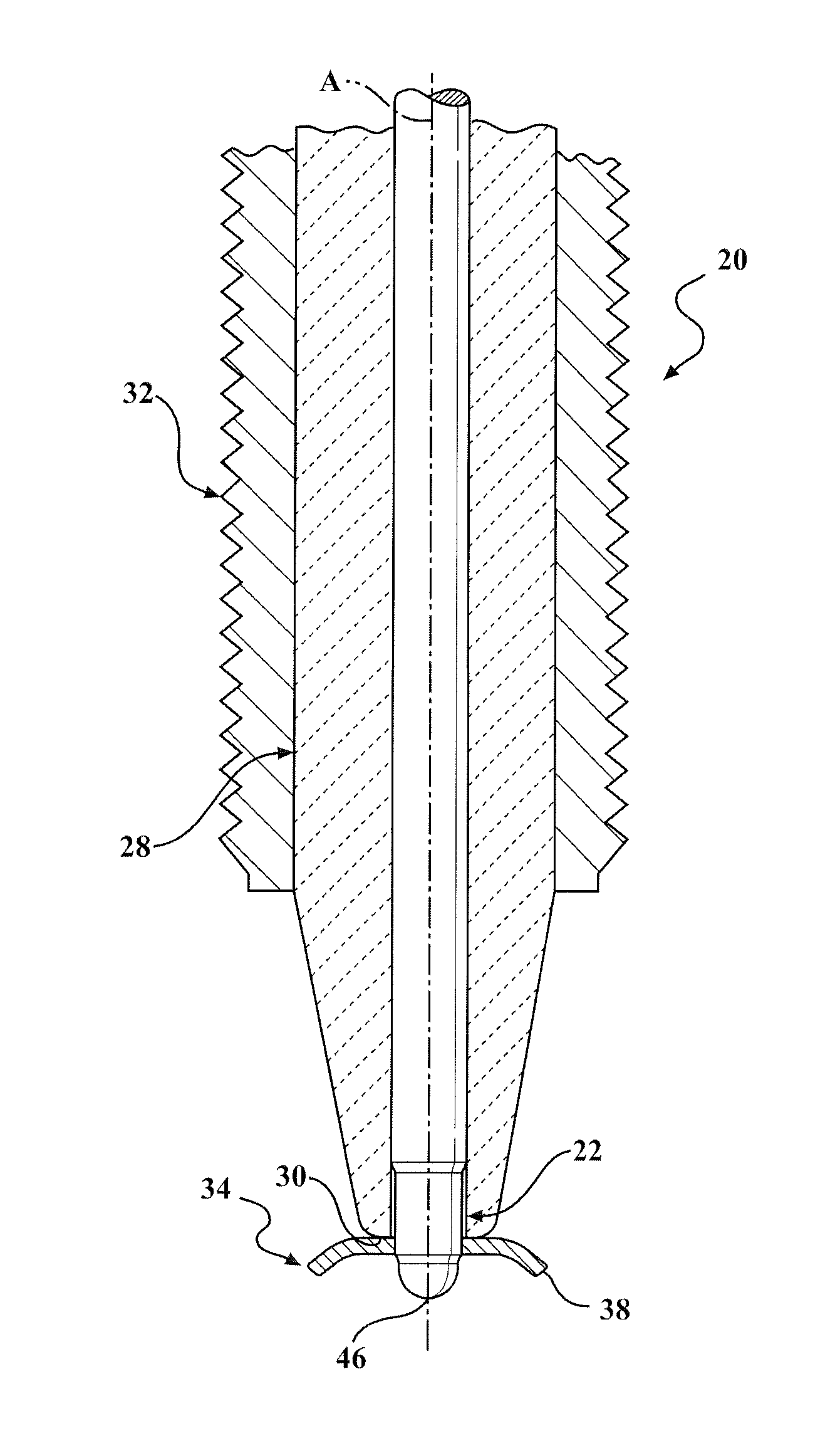
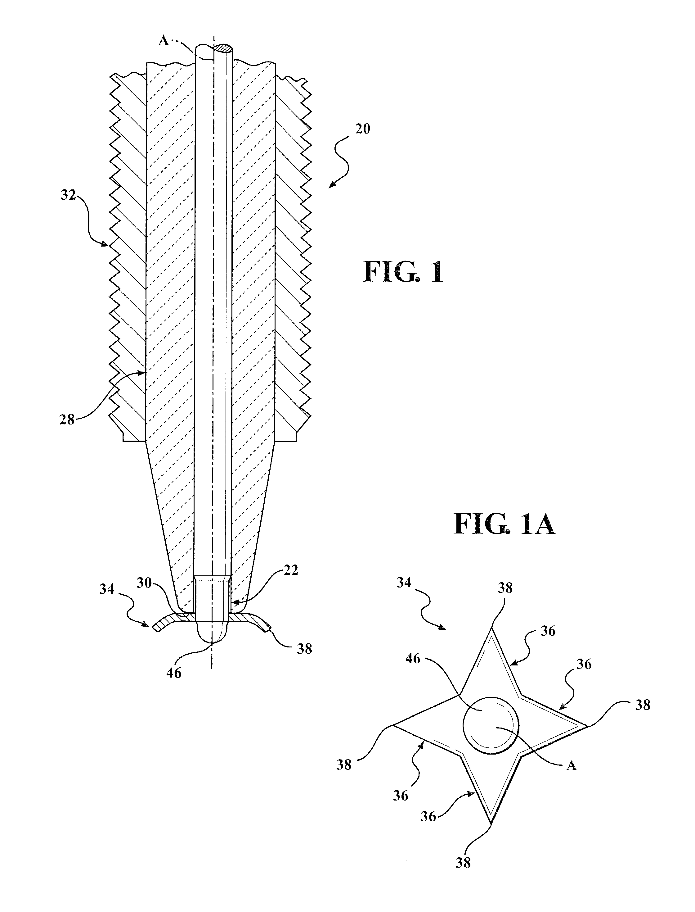
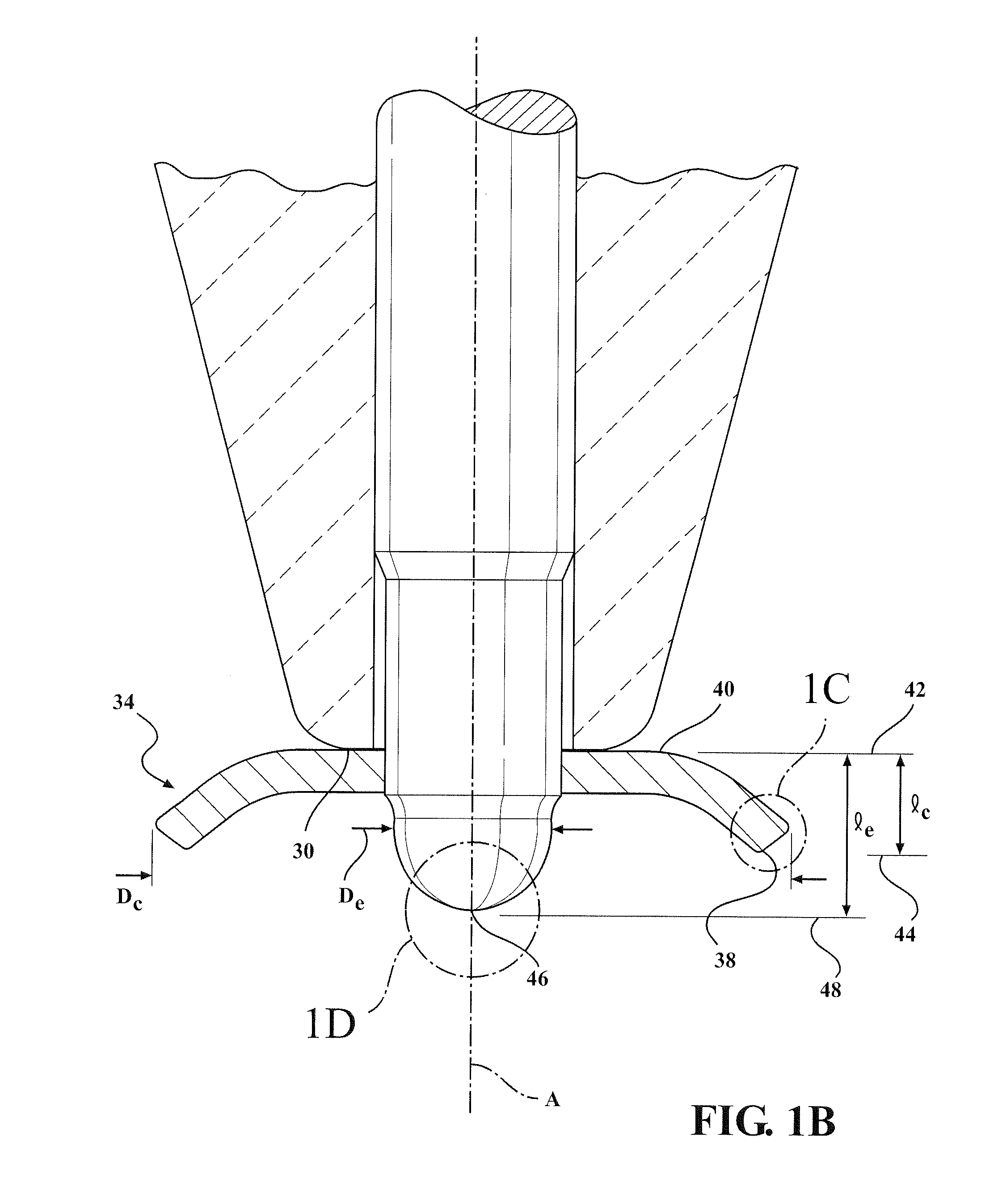
[0033]Referring to the Figures, wherein like numerals indicate corresponding parts throughout the several views, a corona igniter 20 including a central extended member 22 which is capable of providing improved corona discharge 24 and improved combustion performance is generally shown.

[0034]As shown in FIG. 1, the corona igniter 20 includes an electrode extending along a central axis A for emitting an electrical field that forms the corona discharge 24. As in conventional corona igniters, an insulator 28 formed of an electrically insulating material, such as alumina, is disposed around the central extended member 22 and extends along the central axis A to an insulator firing end 30. A shell 32 formed of a metal material is disposed around the insulator 28. The electrode includes the central extended member 22 and a crown 34.

[0035]The crown 34 of the electrode is disposed outwardly of the insulator firing end 30. The crown 34 surrounds the central axis A and the central extended memb...


PUM

PropertyMeasurementUnit
relative permittivityaaaaaaaaaa
radiusaaaaaaaaaa

Abstract

A corona igniter comprises an electrode with a central extended member extending along a central axis and a crown extending radially outwardly from the central extended member. The central extended member has an extended length and the crown has a crown length. The extended length is greater than the crown length such that the extended member approaches a piston more closely than the crown. In addition, the firing tips of the crown each present a first spherical radius which is less than a second spherical radius of the central extended member. Thus, if arcing occurs, it forms from the central extended member, rather than from the crown. Accordingly, the firing tips of the crown experience less wear and remain sharp. In addition, due to the sizes of the spherical radii, corona discharge is more likely to form from the firing tips than from the central extended member.

Description

CROSS REFERENCE TO RELATED APPLICATION[0001]This application claims the benefit of U.S. Provisional Patent Application No. 61 / 799,117, filed Mar. 15, 2013, the entire contents of which is incorporated herein by reference in its entirety.BACKGROUND OF THE INVENTION[0002]1. Field of the Invention[0003]This invention relates generally to a corona igniter for emitting a radio frequency electric field to ionize a fuel-air mixture and provide a corona discharge, a corona discharge ignition system, and methods of manufacturing the same.[0004]2. Related Art[0005]A corona igniter of a corona discharge ignition system receives a voltage from a power source and emits an electrical field that forms a corona to ionize a mixture of fuel and air of an internal combustion engine. The igniter includes an electrode extending longitudinally form an electrode terminal end to an electrode firing end. An insulator is disposed along the center electrode, and a shell is disposed along the insulator.[0006]T...

Claims


Application Information

Patent Timeline
Patent Type & Authority Applications(United States)
IPC IPC(8): F02P23/04
CPCF02P23/04H01T13/50H01T13/467Y10T29/49002H01T21/02H01T19/04H01T19/02H01T21/00H01T19/00
Inventor BURROWS, JOHN A.MIXELL, KRISTAPHER
Owner FEDERAL MOGUL IGNITION
Why Eureka
Try Eureka