Internal secondary fuel rail orifice

a secondary fuel rail and orifice technology, applied in the direction of machines/engines, manufacturing tools, electric control, etc., can solve the problems of inaccurate metering of fuel, degrade adverse impact on the performance of the engine, etc., to reduce the fluctuation of pressure, improve the performance, and reduce the cost of material

Inactive Publication Date: 2014-09-18
DOHERTY ROBERT J
View PDF3 Cites 18 Cited by
  • Summary
  • Abstract
  • Description
  • Claims
  • Application Information

AI Technical Summary

Benefits of technology

[0011]One advantage of embodiments consistent with the present teachings involves improved performance (i.e., reduced pressure fluctuations) as compared to conventional configurations with the same or similar sized fuel rails. Another advantage involves a reduced material cost as compared to conventional, similarly performing but larger-sized fuel rails. A still further advantage involves the ability to meet predetermined performance requirements in a reduced-size package, where conventional approaches, based on enlarged fuel rail configurations, cannot be used. Embodiments consistent with the teachings of the instant disclosure decouple the rail volumes—which feed the injectors—from the pressure swings of the pump, by providing multiple flow restrictors that in turn define multiple pulsation control volumes, as more fully described herein.

Problems solved by technology

An ongoing challenge involves controlling and / or reducing the amount of pressure variation within the fuel rail itself.
Such pressure variation can have an adverse impact on the performance of the engine to which the fuel delivery system is connected.
For example, pressure variation (e.g., pressure waves) may cause inaccurate metering of fuel by the fuel injectors associated with the fuel rail.
This degrades the performance of the engine to which the fuel injectors supply fuel because the desired amount of metered fuel may vary with the amount of pressure within the fuel rail.
In addition, the pressure waves may cause undesirable noise in the fuel rail.
One cause of pressure fluctuation applies to fuel delivery systems that employ a high-pressure fuel pump directly connected to the fuel rail(s).
Such pressure variations have been challenging to accommodate in conventional fuel delivery systems.
While effective, this approach (i) increases the material cost of the fuel rail assembly (i.e., increases the amount of materials needed for the rails), and (ii) increases the physical size of the overall fuel rail assembly (i.e., increases the footprint of the package).
Some applications cannot accommodate the larger-size package, nor tolerate the lower performance of conventional configurations that can be provided in a smaller-sized package.

Method used


Image

  • Internal secondary fuel rail orifice
  • Internal secondary fuel rail orifice
  • Internal secondary fuel rail orifice

Examples


Embodiment Construction

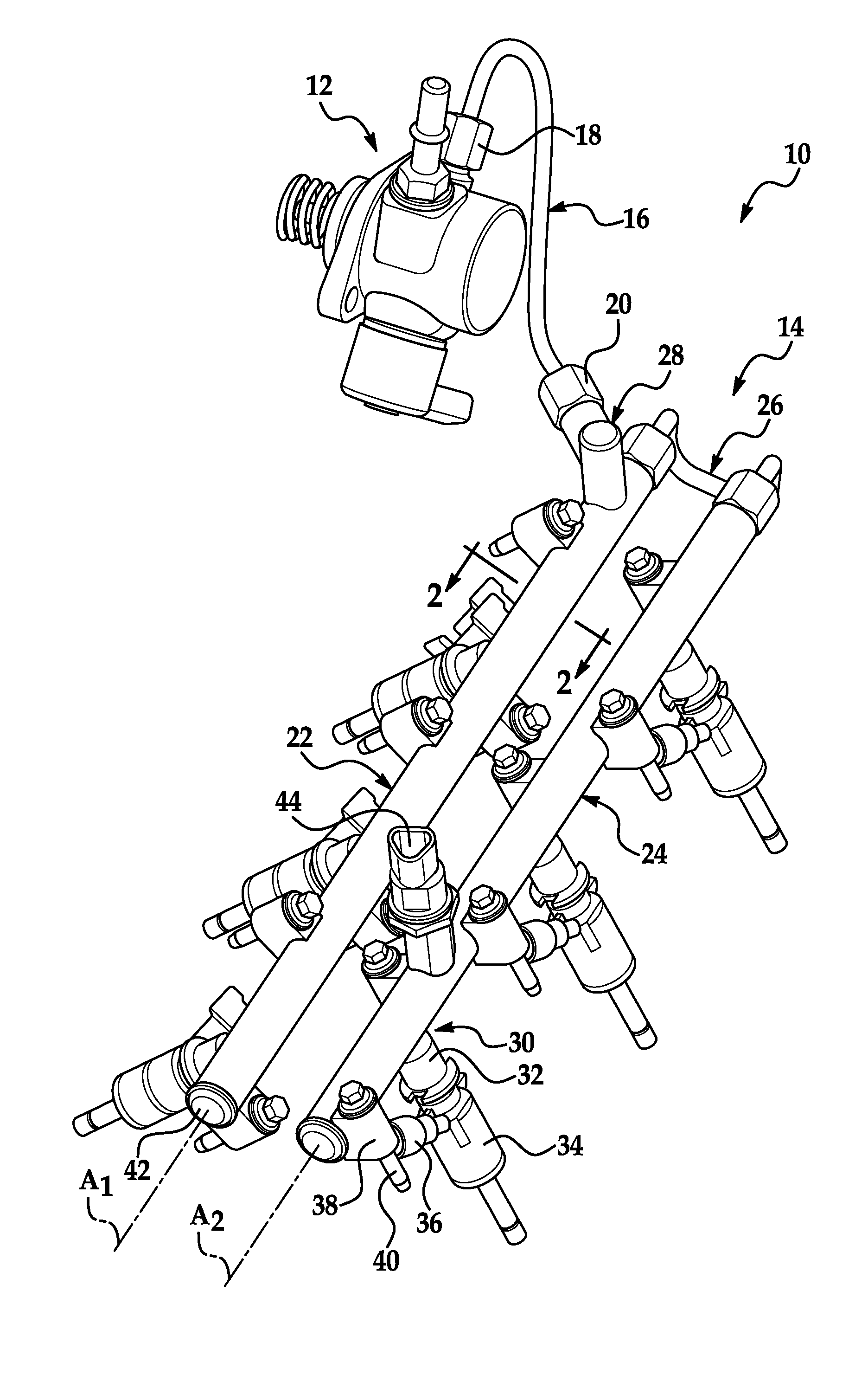
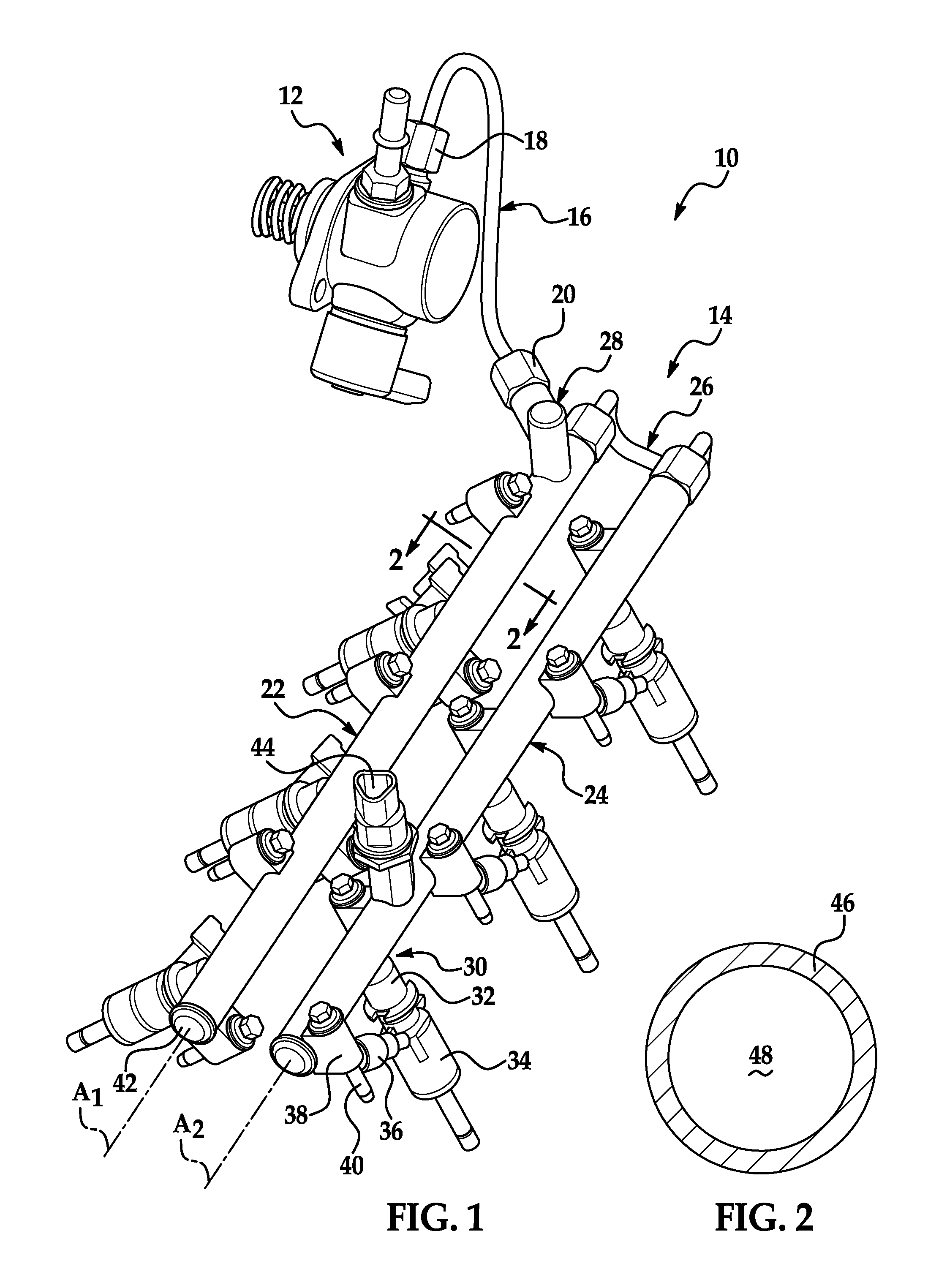
[0025]Referring now to Figures wherein like reference numerals identify identical or similar components in the various views, FIG. 1 is an isometric view of a fuel delivery system 10 in accordance with an embodiment of the instant disclosure. The fluid delivery system and the components and methods of assembling the same will be described, which may have application with respect to a spark-ignited, fuel-injected internal combustion engine; however, other applications are contemplated, as will be recognized by one of ordinary skill in the art.

[0026]The fuel delivery system 10 includes a high-pressure fuel pump 12, a fuel rail assembly 14, and a supply hose or conduit 16 fluidly coupling the pump to the fuel rail assembly 14. The fuel delivery system 10 may be configured for use with a multiple-cylinder internal combustion engine, for example, a six-cylinder engine in the illustrative embodiment. The high-pressure fuel pump 12 is configured with an inlet (shown—but unconnected) for co...


PUM

PropertyMeasurementUnit
pressureaaaaaaaaaa
pressureaaaaaaaaaa
temperaturesaaaaaaaaaa

Abstract

A fuel rail assembly configured for connection to an internal combustion engine includes a first fuel rail, a second fuel rail, and a crossover hose. The first fuel rail includes an inlet having a first flow restrictor and configured to be coupled to a high-pressure pump. The first fuel rail further includes a second flow restrictor disposed in an interior portion that divides the interior into a first rail volume and a remainder volume. The crossover hose includes a third flow restrictor near the end that is connected to the second fuel rail. A first pulsation control volume is defined between the pump and the inlet. A second pulsation control volume is defined to include the remainder volume and the volume in the crossover hose (i.e., between the first and second flow restrictors). The pulsation control volumes reduce pressure fluctuations produced by the high-pressure pump.

Description

CROSS-REFERENCE TO RELATED APPLICATIONS[0001]This application claims the benefit of U.S. provisional application No. 61 / 792,928 filed 15 Mar. 2013, which is hereby incorporated by reference as though fully set forth herein.BACKGROUND[0002]a. Technical Field[0003]The instant disclosure relates to a fuel rail assembly.[0004]b. Background Art[0005]This background description is set forth below for the purpose of providing context only. Therefore, any aspects of this background description, to the extent that it does not otherwise qualify as prior art, is neither expressly nor impliedly admitted as prior art against the instant disclosure.[0006]It is known to provide a fuel delivery system for use with an internal combustion engine. Such a system may include one or more fluid conduits that allow for the delivery of pressurized fuel to multiple fuel injectors. The fluid conduit (i.e., a fuel rail) may include an inlet that is connected to an outlet of a fuel source, for example, in some ...

Claims


Application Information

Patent Timeline
Patent Type & Authority Applications(United States)
IPC IPC(8): F02D41/38F02M63/02
CPCF02M63/0275F02D41/3863Y10T29/49826F02M63/0295F02M55/025F02M61/168F02M2200/8076F02M2200/315F02M2200/8084
Inventor DOHERTY, ROBERT J.
Owner DOHERTY ROBERT J
Why Eureka
Try Eureka