Temperature control system, semiconductor manufacturing device, and temperature control method

a temperature control system and manufacturing device technology, applied in the direction of process control, lighting and heating equipment, instruments, etc., can solve the problems of poor responsiveness to temperature control, deformation of chiller units, and relatively long heating time, and achieve stable temperature control and adequate heat storage volume.

Active Publication Date: 2014-09-18
TOKYO ELECTRON LTD +1
View PDF26 Cites 26 Cited by
  • Summary
  • Abstract
  • Description
  • Claims
  • Application Information

AI Technical Summary

Benefits of technology

[0013]According to an aspect of the present invention, a temperature control system, a semiconductor manufacturing device, and a temperature control method may be provided that can secure adequate heat storage volume and perform stable temperature control by arranging in parallel a plurality of temperature adjustment units including heat storage tanks and circulation pumps and forming a circulation path for circulating fluid stored in the heat storage tanks of the temperature control units.

Problems solved by technology

However, heating takes a relatively long period of time due to the cooling effect of the chiller unit, and such poor responsiveness to temperature control has been a problem.
However, in such a case, the cooling capacity of the chiller unit is degraded, the cooling speed of the system is decreased, and temperature controllability is degraded.
However, a high frequency power leak current is increased in such a case.
That is, in a semiconductor manufacturing device, when a heater is embedded within an electrostatic chuck that is arranged on a stage and is applied a high frequency power, the high frequency power may be leaked outside via a heater line, and the leak current increases as the capacity of the heater is increased.
However, when the capacity of the heater is increased, the size of the heater power supply filter has to be increased as well.
Thus, when the size of the heater power supply filter is increased, the heater power supply filter takes up extra space thereby reducing the space for mounting other components.

Method used


Image

  • Temperature control system, semiconductor manufacturing device, and temperature control method
  • Temperature control system, semiconductor manufacturing device, and temperature control method
  • Temperature control system, semiconductor manufacturing device, and temperature control method

Examples


Embodiment Construction

[0022]In the following, embodiments of the present invention are described with reference to the accompanying drawings. Note that elements having substantially the same functions or features may be given the same reference numerals and overlapping descriptions thereof may be omitted.

[0023][Overall Configuration of Semiconductor Manufacturing Device and Temperature Control System]

[0024](Semiconductor Manufacturing Device)

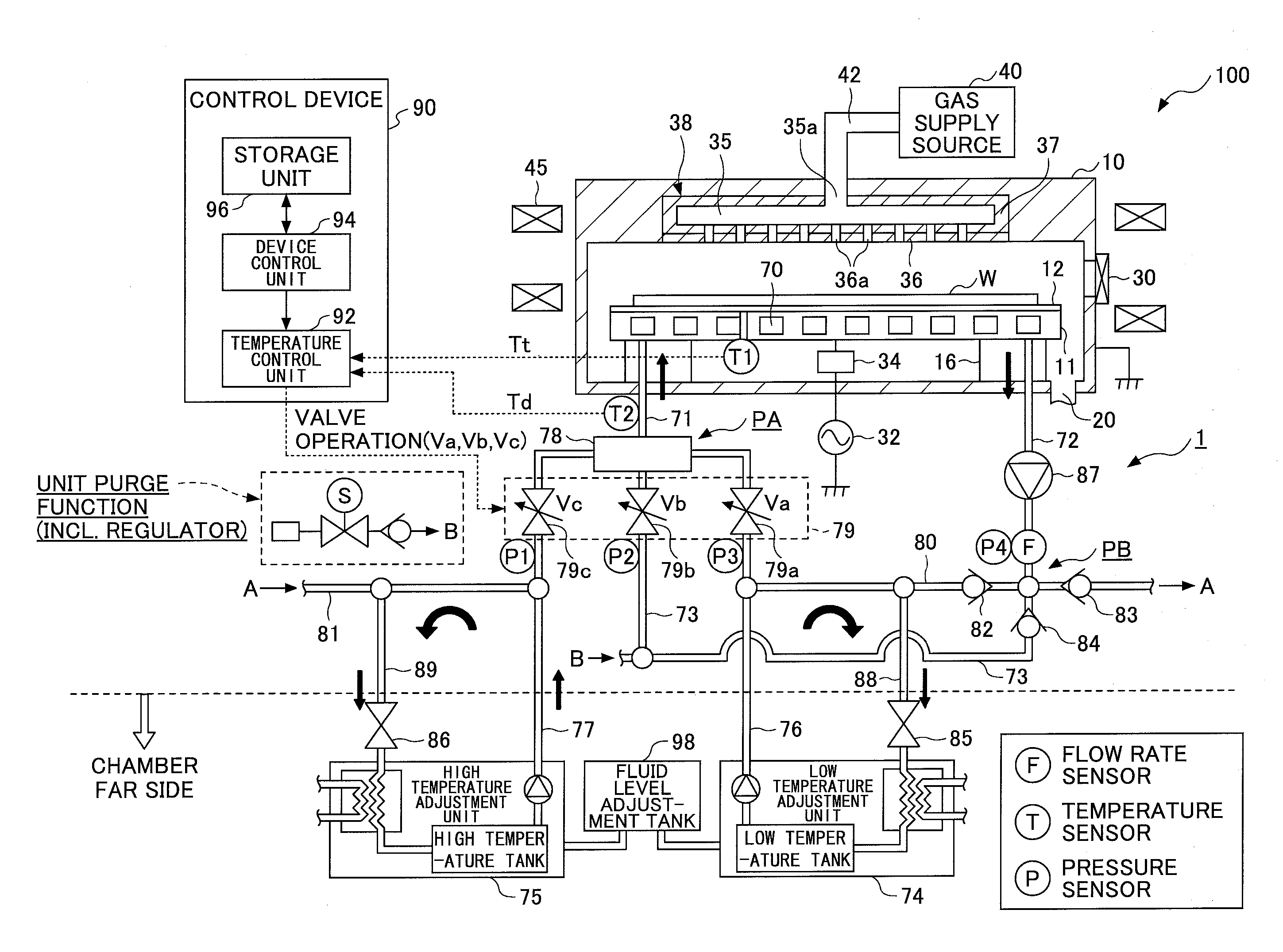
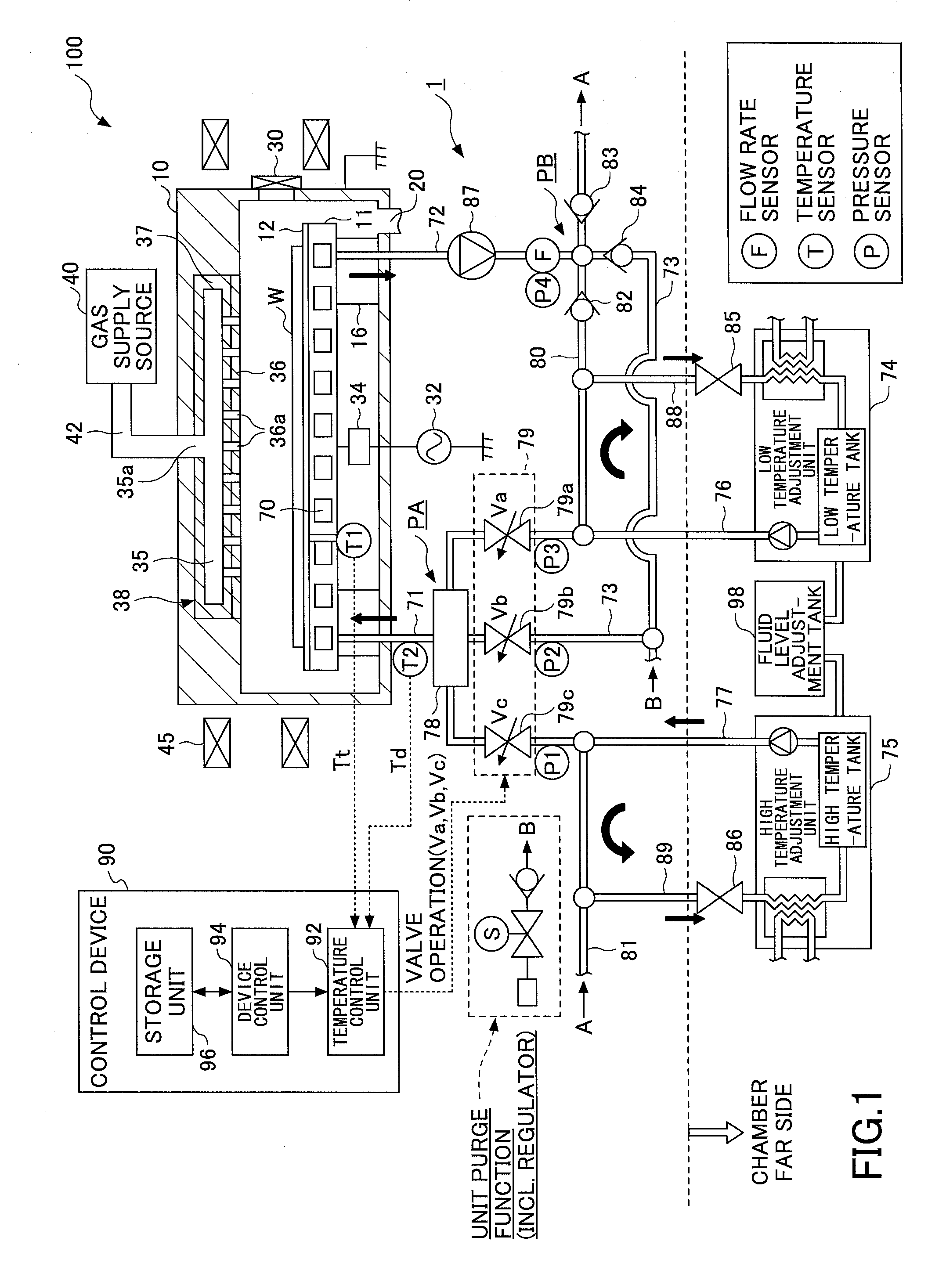
[0025]An overall configuration of a temperature control system 1 according to an embodiment of the present invention is described below with reference to FIG. 1. In the present embodiment, temperature control of a semiconductor manufacturing device 100 is implemented by the temperature control system 1.

[0026]The semiconductor manufacturing device 100 illustrated in FIG. 1 is a RIE (reactive ion etching) type plasma processing device and includes a cylindrical processing chamber (chamber) 10 made of metal such as aluminum or stainless steel, for example. The processin...


PUM


Abstract

A temperature control system includes a first temperature adjustment unit storing fluid at a first temperature; a second temperature adjustment unit storing fluid at a second temperature higher than the first temperature; a low-temperature flow path for passing fluid supplied from the first temperature adjustment unit; a high-temperature flow path for passing fluid supplied from the second temperature adjustment unit; a bypass flow path for circulating fluid; a combination flow path for passing fluid from the low-temperature flow path, the high-temperature flow path, and the bypass flow path merged at a merging part; a temperature adjustment part that passes fluid from the combination flow path and cools/heats a member of a semiconductor manufacturing device; and a control device that controls valve positions of variable valves attached to the three flow paths upstream of the merging part and adjusts the flow rate distribution ratio for the three flow paths.

Description

TECHNICAL FIELD[0001]The present invention relates to a temperature control system, a semiconductor manufacturing device, and a temperature control method.BACKGROUND ART[0002]Temperature control of a workpiece placed on an electrostatic chuck is generally performed using a heater and a chiller unit arranged within the electrostatic chuck. In such a system, cooling is performed by circulating a coolant at a predetermined temperature through a coolant pipe of the chiller unit and heating is performed by applying an alternating current to the heater. Through such heating by the heater and cooling by the chiller unit, the wafer temperature of a wafer placed on the electrostatic chuck may be adjusted to a desired temperature.[0003]In such a system, a low-temperature coolant (fluid) is arranged to be flowing within the chiller unit at a constant flow rate. To raise the temperature in such a state, the heater that is embedded within a stage has to be heated. However, heating takes a relati...

Claims


Application Information

Patent Timeline
Patent Type & Authority Applications(United States)
IPC IPC(8): H01L21/67
CPCH01L21/67248H01L21/67103H01L21/67109G05D23/1934
Inventor KOBAYASHI, ATSUSHITABUCHI, ATSUHIKOWAKAI, HIDEKIITOH, KAZUTOSHIHIROSE, YASUHISANISHIKAWA, KEIICHIMINATANI, TAKAHIRO
Owner TOKYO ELECTRON LTD
Why Eureka
Try Eureka