Pulse Synchronization By Monitoring Power In Another Frequency Band

Active Publication Date: 2014-09-18
MKS INSTR INC
View PDF38 Cites 49 Cited by
  • Summary
  • Abstract
  • Description
  • Claims
  • Application Information

AI Technical Summary

Benefits of technology

[0054]With reference to FIG. 12, FIG. 12 indicates various embodiments in which a matching network 34 can be used to filter out the master frequency. In such various embodiments, it may be necessary to locate the detector 40a, 40b between the matching network that functions as the filter and the plasma chamber 36. The detector of f1 40a and f2 40b as shown in FIG. 12 is located in the matching network. The detector 40a, 40b thus detects power at f1 and f2 prior to the reflected signal passing through

Problems solved by technology

As plasma systems have evolved, many new challenges for both continuous wave and pulsed RF control exist to meet the specifications required to meet critical manufacturing specifications.
The success of multiple power sources to independently control plasma parameters such as ion flux and ion energy to the surface of a processed material

Method used


Image

  • Pulse Synchronization By Monitoring Power In Another Frequency Band
  • Pulse Synchronization By Monitoring Power In Another Frequency Band
  • Pulse Synchronization By Monitoring Power In Another Frequency Band

Examples


Embodiment Construction

[0029]Example embodiments will now be described more fully with reference to the accompanying drawings.

[0030]Example embodiments are provided so that this disclosure will be thorough, and will fully convey the scope to those who are skilled in the art. Numerous specific details are set forth such as examples of specific components, devices, and methods, to provide a thorough understanding of embodiments of the present disclosure. It will be apparent to those skilled in the art that specific details need not be employed, that example embodiments may be embodied in many different forms and that neither should be construed to limit the scope of the disclosure. In some example embodiments, well-known processes, well-known device structures, and well-known technologies are not described in detail.

[0031]The terminology used herein is for the purpose of describing particular example embodiments only and is not intended to be limiting. As used herein, the singular forms “a”, “an” and “the” ...


PUM

PropertyMeasurementUnit
Timeaaaaaaaaaa
Frequencyaaaaaaaaaa

Abstract

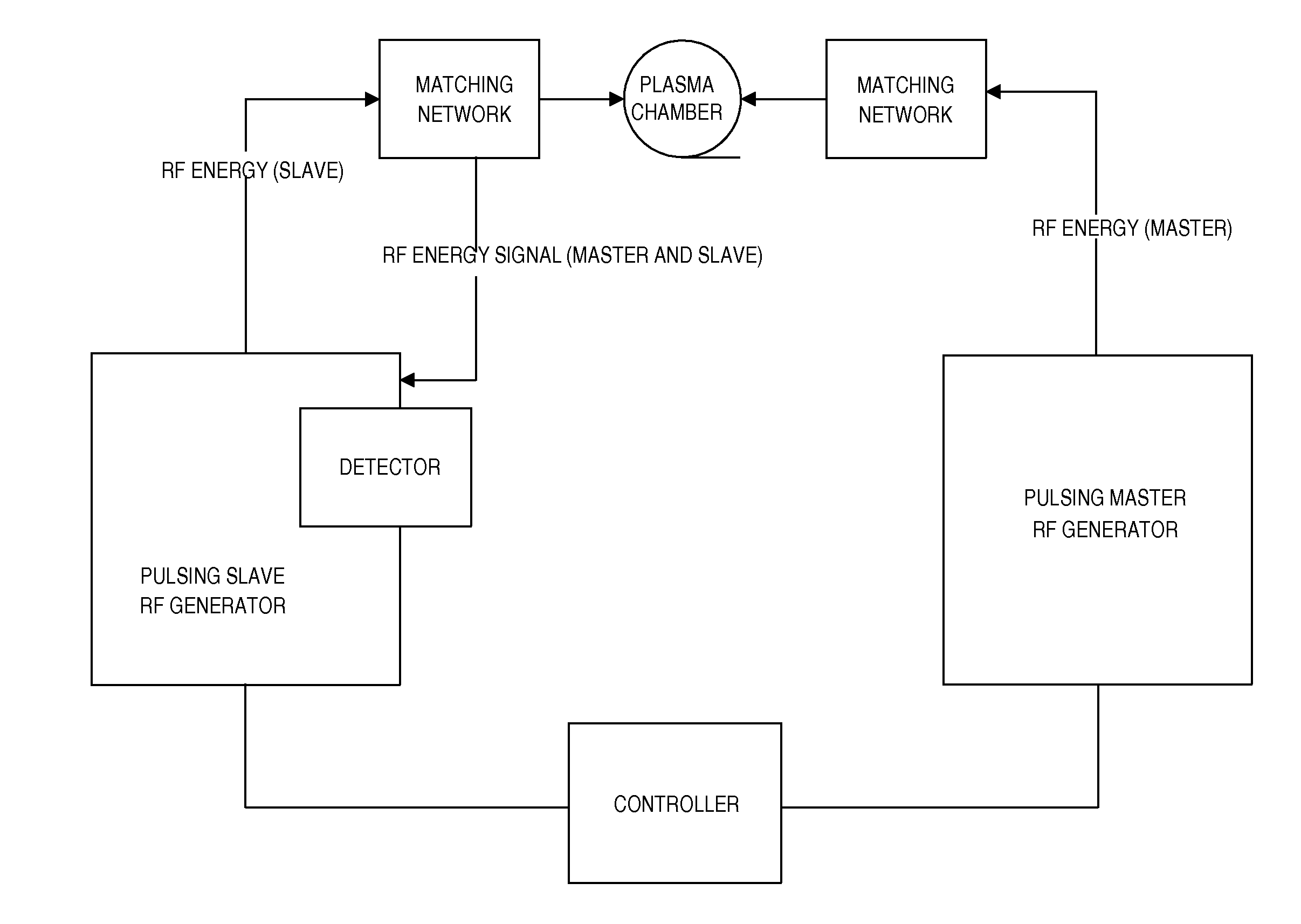
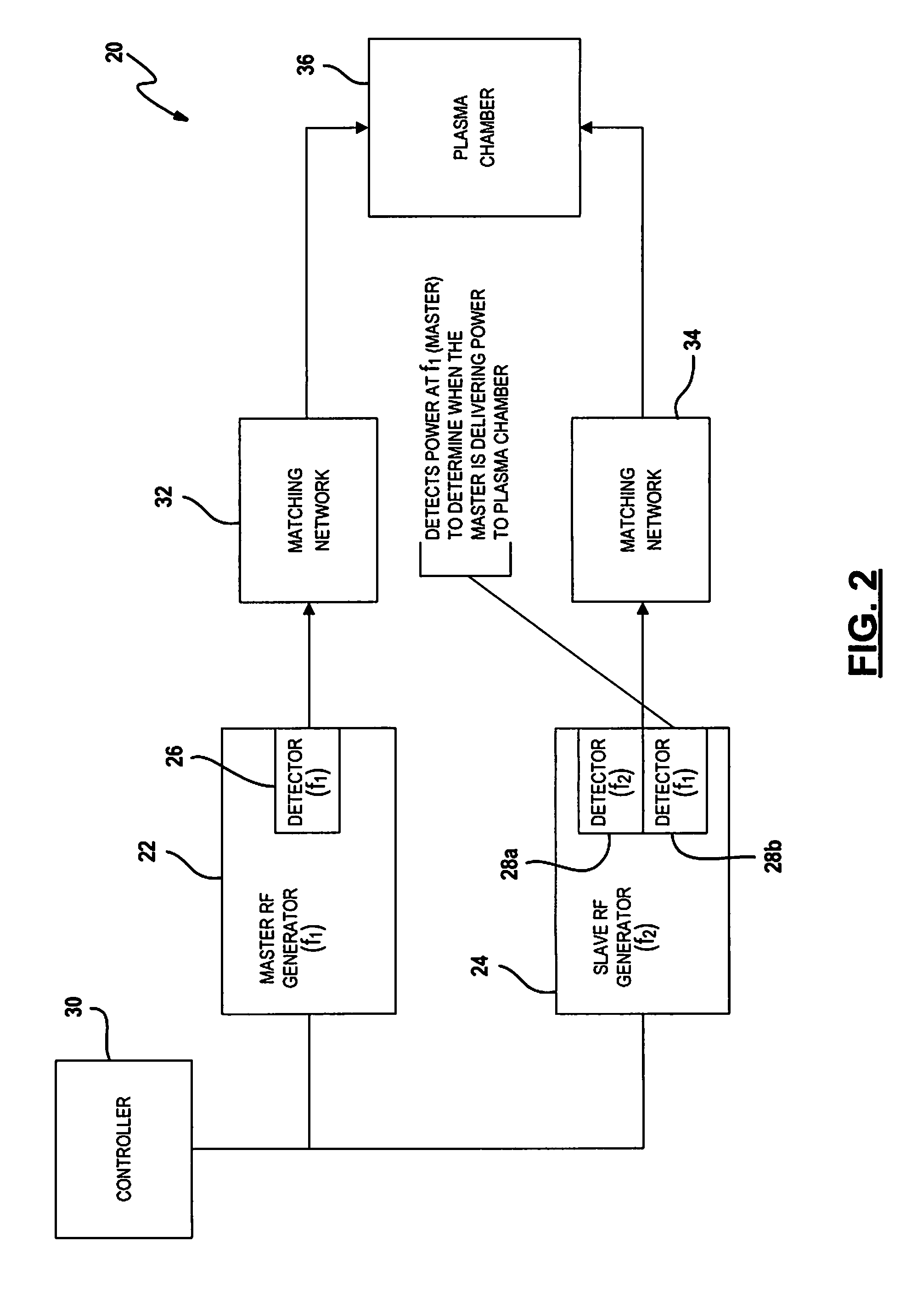
A radio frequency (RF) power delivery system includes a first RF generator and a second RF generator. The first RF generator operates as a master RF generator, and the second RF generator operates as a slave RF generator. The slave RF generator includes a detector for sensing an electrical characteristic of the RF signal of the slave RF generator. The slave RF generator also includes a detector for sensing an electrical characteristic of the RF signal from the master RF generator. Operation of the slave RF generator is controlled by a host or controller. The host or controller operates the slave RF generator in accordance with electrical properties determined by the second detector.

Description

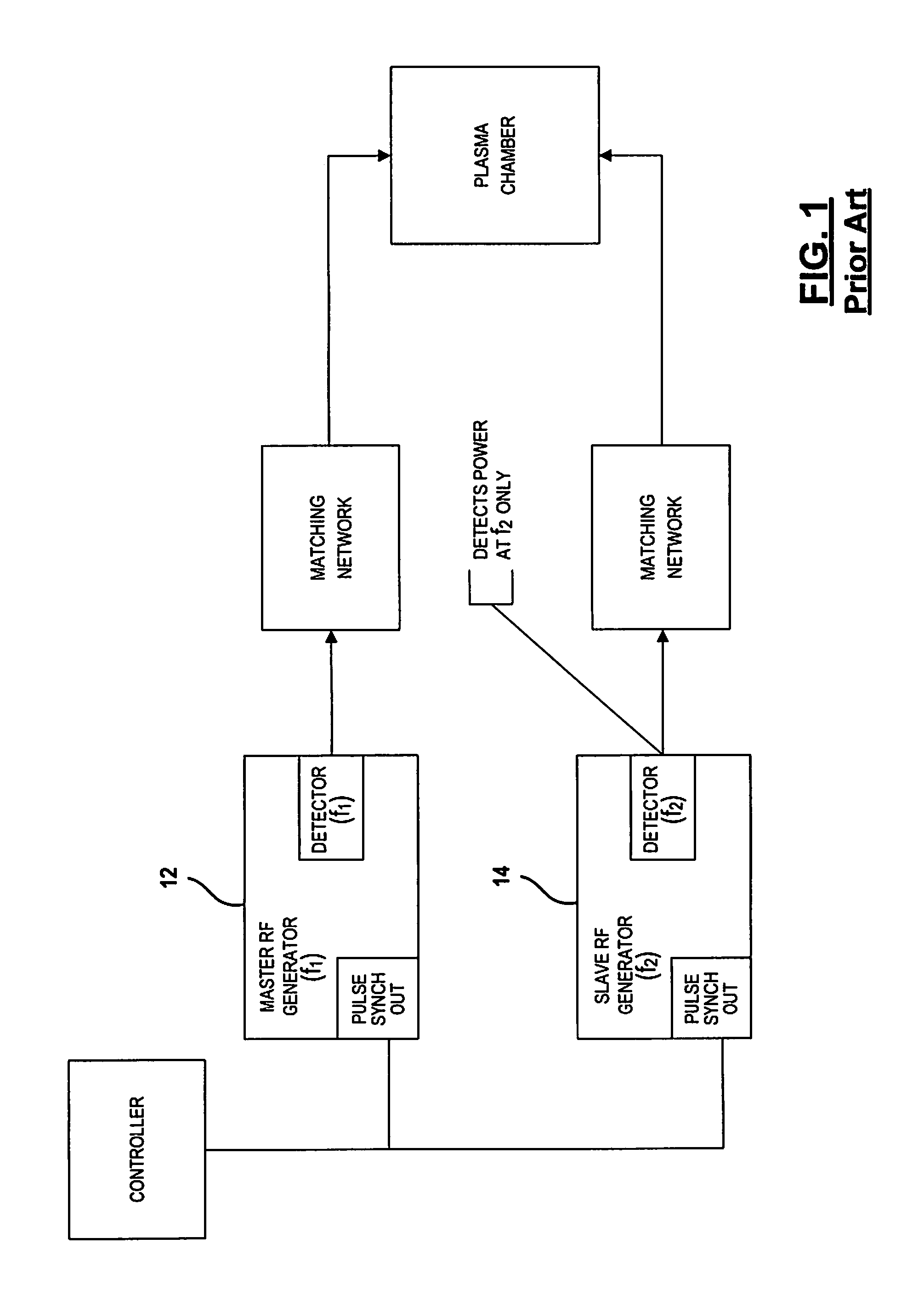
FIELD[0001]The present disclosure relates to efficiently synchronizing pulsing between RF generators.BACKGROUND[0002]The background description provided herein is for the purpose of generally presenting the context of the disclosure. Work of the presently named inventors, to the extent the work is described in this background section, as well as aspects of the description that may not otherwise qualify as prior art at the time of filing, are neither expressly nor impliedly admitted as prior art against the present disclosure.[0003]Plasma etching is frequently used in semiconductor fabrication. In plasma etching, ions are accelerated by an electric field to etch exposed surfaces on a substrate. The electric field is generated based on RF power signals generated by a radio frequency (RF) generator of a RF power system. The RF power signals generated by the RF generator must be precisely controlled to effectively execute plasma etching.[0004]A RF power system may include a RF generator...

Claims


Application Information

Patent Timeline
IPC IPC(8): B23K10/00
CPCB23K10/00C23F4/00H01J37/32183H01J37/32165H01J37/32082B23K20/004B23K20/10B23K2101/42
Inventor NELSON, NICHOLASCOUMOU, DAVID J.
Owner MKS INSTR INC
Why Eureka
Try Eureka