Ion trap mobility spectrometer and method of using the same

a technology of mobility spectrometer and ion trap, which is applied in the direction of dispersed particle separation, instruments, separation processes, etc., can solve the problems of poor resolution, expansion and distortion of the ion disk, and negative impact on the subsequent analysis of the peak trace, so as to reduce the peak tailing portion.

Active Publication Date: 2014-09-18
RAPISCAN SYST INC (US)
View PDF2 Cites 14 Cited by
  • Summary
  • Abstract
  • Description
  • Claims
  • Application Information

AI Technical Summary

Benefits of technology

[0008]In one aspect, an apparatus for detecting constituents in a sample is provided. The apparatus includes a casing and an ionization chamber at least partially defined by the casing. The ionization chamber is configured to generate and store ions. The apparatus also includes an ion collector positioned downstream from the ionization chamber. The apparatus further includes a spectral analysis device coupled to the ion collector. The spectral analysis device is configured to generate a detection spectrum representative of ions collected at the ion collector. The detection spectrum includes an analyte peak portion and a peak tailing portion. The apparatus also includes a control system coupled to the ionization chamber. The control system is configured to generate a first pulse within the ionization chamber having a first polarity to initiate a discharge of at least a portion of the stored ions from the ionization chamber. The control system is also configured to generate a second pulse within the ionization chamber having a second polarity opposite the first polarity of the first pulse generated substantially immediately after the first pulse. The second pulse is configured to reduce the peak tailing portion.

Problems solved by technology

Such trailing ion tail defines an asymmetric peak trace on spectral analysis equipment that negatively impacts the subsequent analysis of the peak trace.
Further, in many known ITMS detection systems, as the disk of ions traverses the drift region, the separation of the high-mobility analytes from the low-mobility analytes induces expansion and distortion of the ion disk.
The peaks on the trace thus generated on the spectral analysis equipment is distorted with poor resolution and are difficult to analyze.
Moreover, in many of the known ITMS detection systems, there is no precise control over the width of the ion disk injected into the drift region.
Fundamentally, this is due to inconsistent, and sometimes, incomplete clearing out of the ionization chamber due to nonhomogeneity of the electric field induced in the ionization chamber, e.g., low field regions at the back of the ionization chamber.
Increasing the strength of the electric field to empty the ionization chamber more rapidly and to decrease the transit time through the drift region increases the potential for ion leakage from the ionization chamber through the retainer grid after the kickout pulse.
Such ion loss decreases the resolution of the spectral peaks to be analyzed.
Further, increasing the field strength for a kickout pulse of reduced width to eject both high-mobility ions and low-mobility ions may result in the ions just inside the chamber proximate the retention grid to induce an electric field of their own that opposes the retention field generated by the retention grid.

Method used


Image

  • Ion trap mobility spectrometer and method of using the same
  • Ion trap mobility spectrometer and method of using the same
  • Ion trap mobility spectrometer and method of using the same

Examples


Embodiment Construction

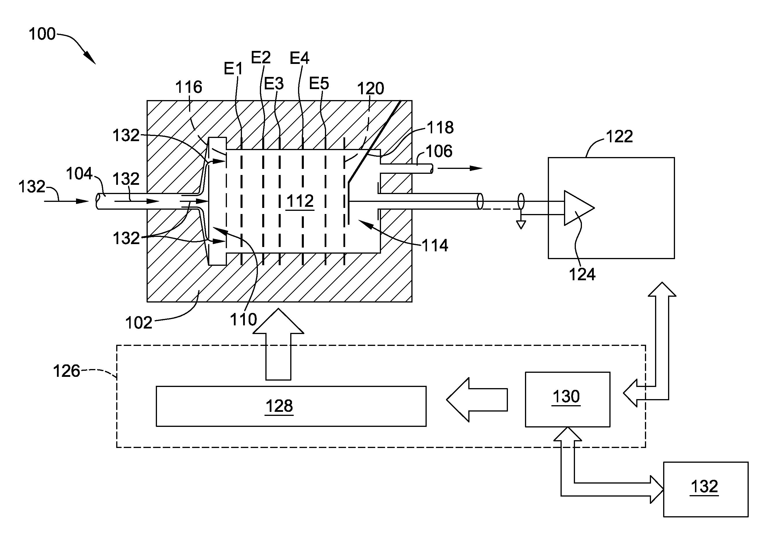
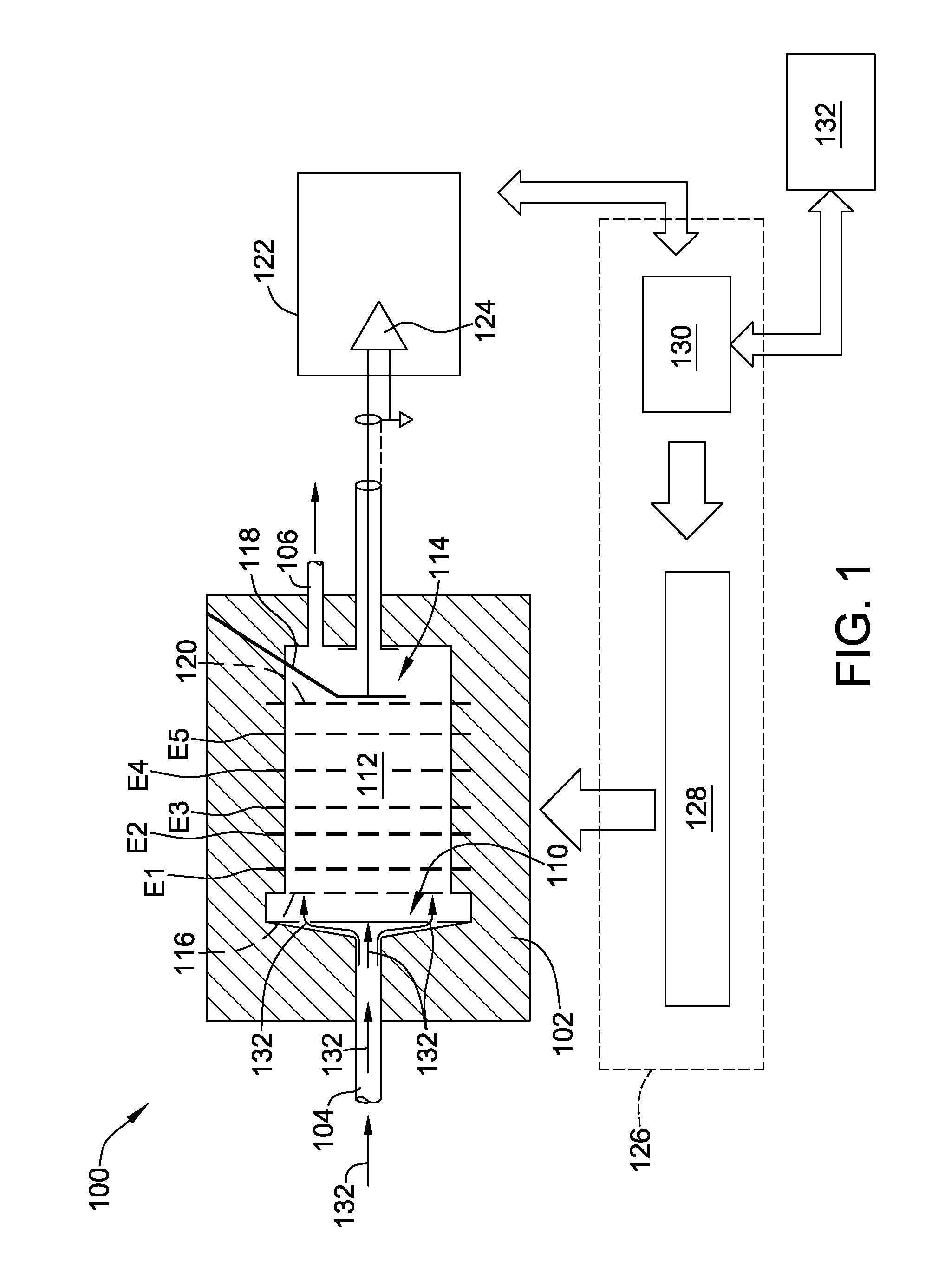
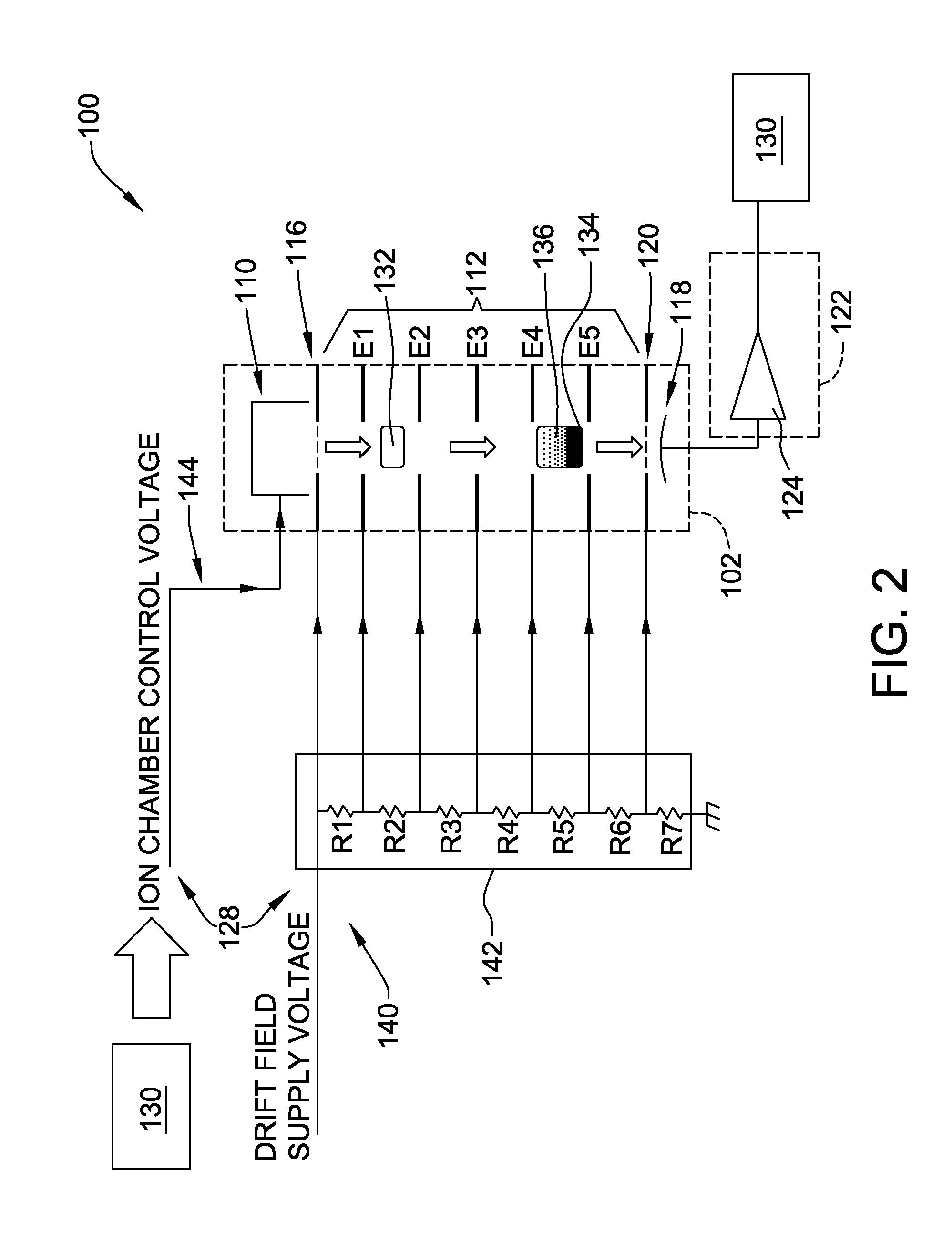
[0022]The embodiments described herein provide a cost-effective system and method for improving detection of materials of interest from an object or person. The systems and methods described herein induce a first electric field across an ionization chamber for a first temporal period, i.e., a first pulse. The first pulse has a first polarity, thereby ejecting at least a portion of the ions from the ionization chamber. Also, the systems and methods described herein induce a second electric field across the ionization chamber substantially immediately following the first temporal period. The second electric field has a second polarity opposite the first polarity, i.e., a second pulse, thereby substantially decreasing the ejection of the at least a portion of the ions from the ionization chamber. Further, the systems and methods described herein reduce a tailing portion of a spectral peak associated with the ions ejected from the ionization chamber as a result of the second field pulse...


PUM

PropertyMeasurementUnit
polarityaaaaaaaaaa
voltage amplitudeaaaaaaaaaa
temporal widthaaaaaaaaaa

Abstract

An apparatus for detecting constituents in a sample includes a casing and an ionization chamber defined by the casing. The apparatus also includes an ion collector positioned downstream of the ionization chamber. The apparatus further includes a spectral analysis device coupled to the ion collector. The spectral analysis device is configured to generate a detection spectrum representative of ions collected at the ion collector. The detection spectrum includes an analyte peak portion and a peak tailing portion. The apparatus also includes a control system that is configured to generate a first pulse having a first polarity to initiate a discharge of stored ions from the ionization chamber. The control system is also configured to generate a second pulse substantially immediately after the first pulse. The second pulse has a second polarity opposite the first polarity and is configured to reduce the peak tailing portion.

Description

CROSS REFERENCE TO RELATED APPLICATIONS[0001]This application claims the priority of Provisional Patent Application Ser. No. 61 / 800,044, entitled “ION TRAP MOBILITY SPECTROMETER AND METHOD OF USING THE SAME”, which was filed on Mar. 15, 2013, and is hereby incorporated by reference in its entirety.BACKGROUND OF THE INVENTION[0002]The embodiments described herein relate generally to an ion trap mobility spectrometer (ITMS) and, more particularly, to an ITMS for enhancing detection of materials of interest through enhanced resolution of high-mobility ions and low-mobility ions.[0003]At least some known spectroscopic detection devices include ion trap mobility spectrometer (ITMS) detection systems. Such ITMS detection systems are used to detect trace portions of materials of interest, e.g., residues. At least some known ITMS detection systems include an ionization chamber that produces positive ions, negative ions, and free electrons. As the ions are being generated in the ionization c...

Claims


Application Information

Patent Timeline
Patent Type & Authority Applications(United States)
IPC IPC(8): G01N27/62
CPCG01N27/622H01J49/427
Inventor GOEDECKE, LYNDON KARL
Owner RAPISCAN SYST INC (US)
Why Eureka
Try Eureka