Ultra high efficiency power generation system and water turbine

Inactive Publication Date: 2014-09-18
ANDREIS BRUNO PETER
View PDF1 Cites 26 Cited by
  • Summary
  • Abstract
  • Description
  • Claims
  • Application Information

AI Technical Summary

Benefits of technology

[0006]An object of the invention is to provide a turbine system which includes (1) an augmenter which

Problems solved by technology

Thus, the design problem reduces to optimization of a single set of two

Method used


Image

  • Ultra high efficiency power generation system and water turbine
  • Ultra high efficiency power generation system and water turbine
  • Ultra high efficiency power generation system and water turbine

Examples


Embodiment Construction

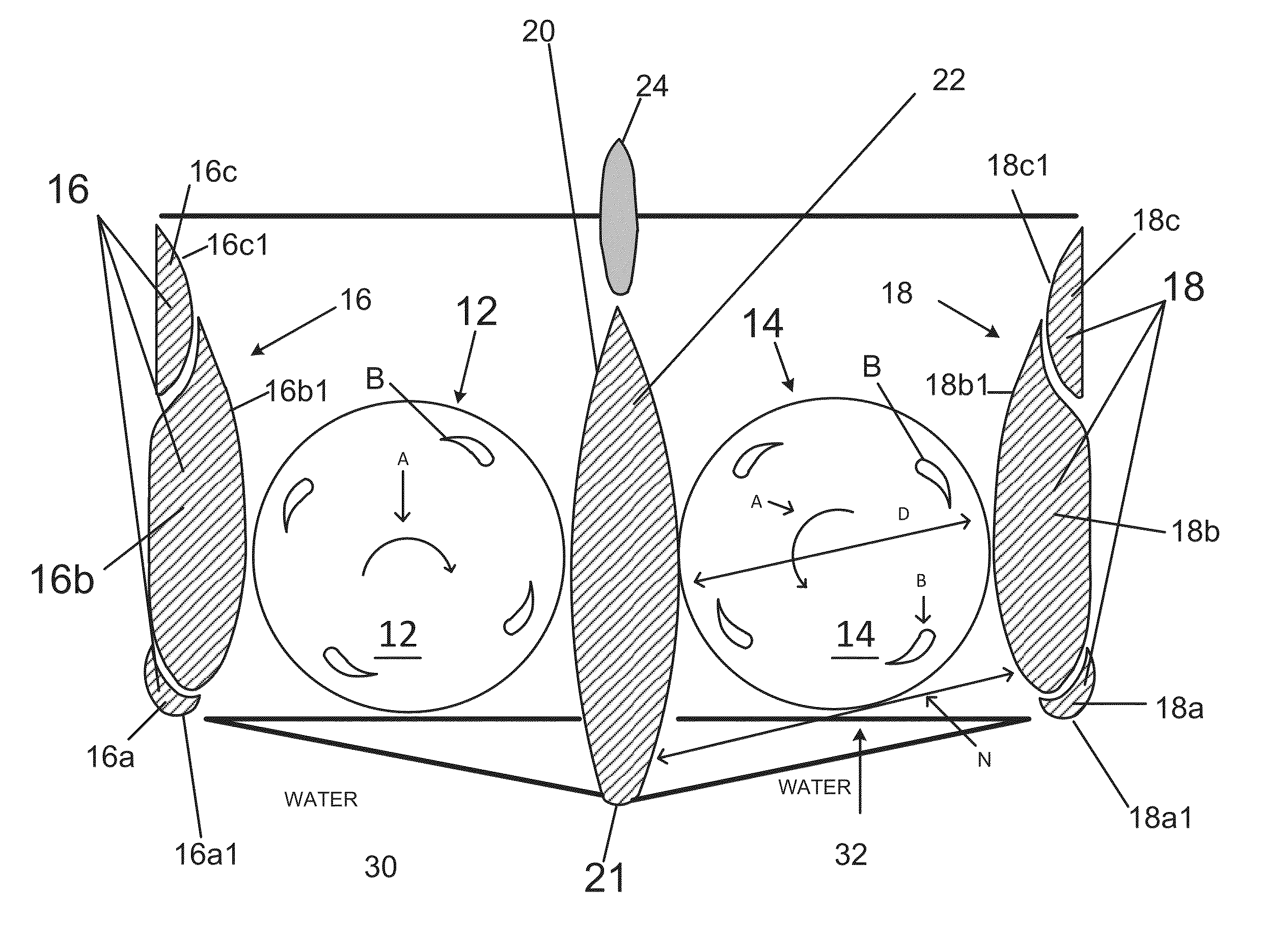
[0063]This disclosure relates to an electrical power generation system 10. Before describing in detail the system 10, some general principals and features will be introduced for ease of understanding.

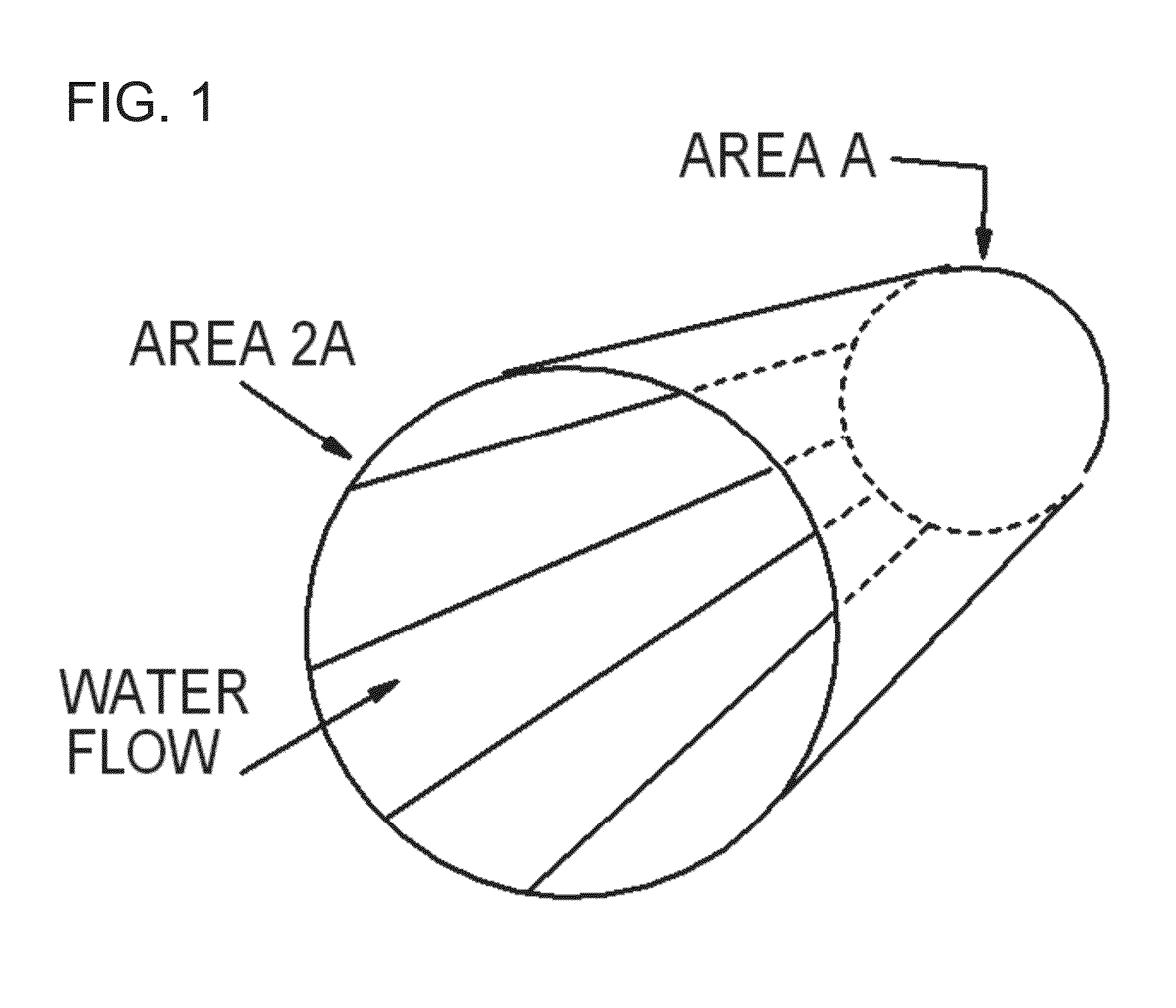
[0064]FIG. 1 illustrates a simplified nozzle or venturi in which incoming water first encounters a cross sectional area of 2A, and then, at a throat of the nozzle, encounters a cross sectional area of half that value namely A as indicated. According to the Continuity Principle, the velocity of the water must double at area A, at the throat, because to maintain continuity, the amount of mass crossing boundary area A must equal that crossing area 2A.

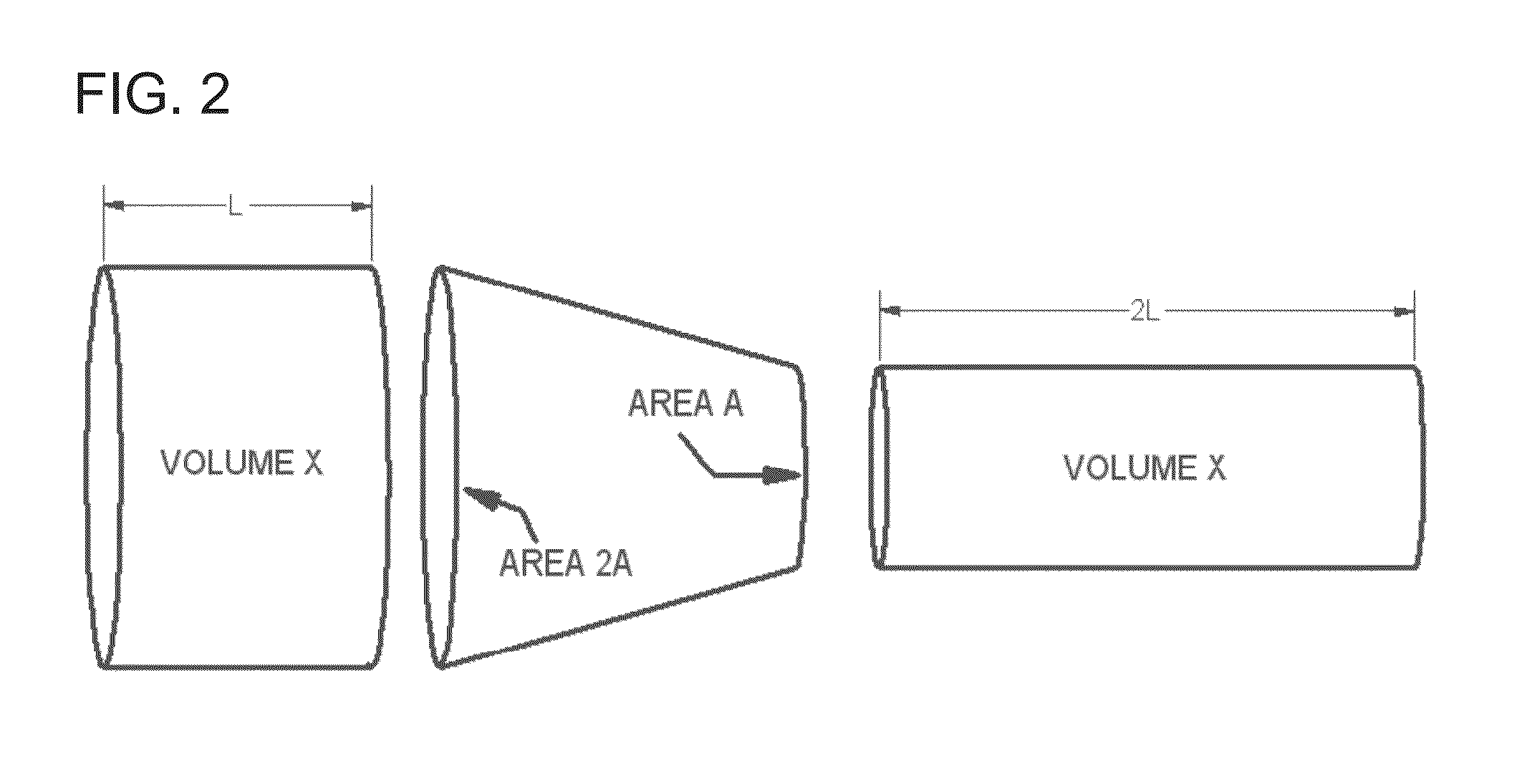
[0065]From another perspective, which considers volume rather than mass, because water is considered generally incompressible, the Continuity Principle requires that the volume crossing area A must also equal the volume crossing area 2A. Because the volumes must be equal, the velocity crossing area A must be generally double the velocity cross...


PUM


Abstract

An electrical generation system. A floating vessel is anchored in flowing water. Inlets in the hull of the vessel capture flowing water and direct the water to one or more turbines. The system is designed so that all flows are two-dimensional to the extent possible. The latter feature greatly simplifies both design and construction.

Description

I. BACKGROUND OF THE INVENTION[0001]1. Field of the Invention[0002]This invention relates to power generation systems that utilize water turbines which generate electricity.[0003]2. Description of the Related Art[0004]Numerous approaches have been proposed for the generation of electricity from (1) ocean tides and (2) river currents. However, a common problem in these approaches is high cost: an efficient water turbine, which extracts a large fraction of the energy available in the water, is expensive to design and construct.[0005]The invention proposes a lower-cost and different solution.II. SUMMARY OF THE INVENTION[0006]An object of the invention is to provide a turbine system which includes (1) an augmenter which increases water velocity, and (2) a low cost turbine which derives power from the accelerated water.[0007]In one form of the invention, a two-dimensional channel, augmenter or nozzle accelerates water. A two-dimensional turbine is located in the vicinity of a throat of t...

Claims


Application Information

Patent Timeline
IPC IPC(8): B63B1/32G06F17/50F03B13/10F03B11/02F03B3/12
CPCB63B1/32F03B11/02G06F17/50F03B3/121F03B13/10B63B2035/4466F03B13/264F03B17/063F05B2240/133F05B2240/301F05B2240/93F05B2240/932Y02E10/30Y02E10/20
Inventor ANDREIS, BRUNO PETERELLIOTT, STEPHENDI FELICE, FABIOSALVATORE, FRANCESCOLA GALA, FRANCESCOGRECO, LUCATESTA, CLAUDIOCALCAGNI, DANILODUBBIOSO, GIULIO ANTONINO
Owner ANDREIS BRUNO PETER
Why Eureka
Try Eureka