Systems and Methods for Optimizing Amplifier Operations

a technology of amplifier operation and optimization method, applied in the field of amplifiers, can solve problems such as size and power consumption problems, adversely affecting the output signal, and unstable control loops

Active Publication Date: 2014-09-18
PSEMI CORP
View PDF6 Cites 77 Cited by
  • Summary
  • Abstract
  • Description
  • Claims
  • Application Information

AI Technical Summary

Benefits of technology

[0004]According to a first aspect of the present disclosure, a system for optimizing amplifier operations is provided. The system includes an amplifier configured to receive an input signal and generate therefrom, an output signal having a desired characteristic; and also includes a feed-forward control circuit configured to receive said input signal, analyze said input signal, and generate a control signal that is provided to the amplifier for impressing the desired characteristic upon said output signal.

Problems solved by technology

However, this gain feedback operation may result in adversely impacting the output signal, for example the control loop may be too slow or may become unstable.
Furthermore, closed loop operation typically involves more active and / or passive circuit blocks, which can lead to size and power consumption issues.
Closed loop systems also have limited bandwidth, and may be susceptible to interference issues as well.

Method used


Image

  • Systems and Methods for Optimizing Amplifier Operations
  • Systems and Methods for Optimizing Amplifier Operations
  • Systems and Methods for Optimizing Amplifier Operations

Examples


Embodiment Construction

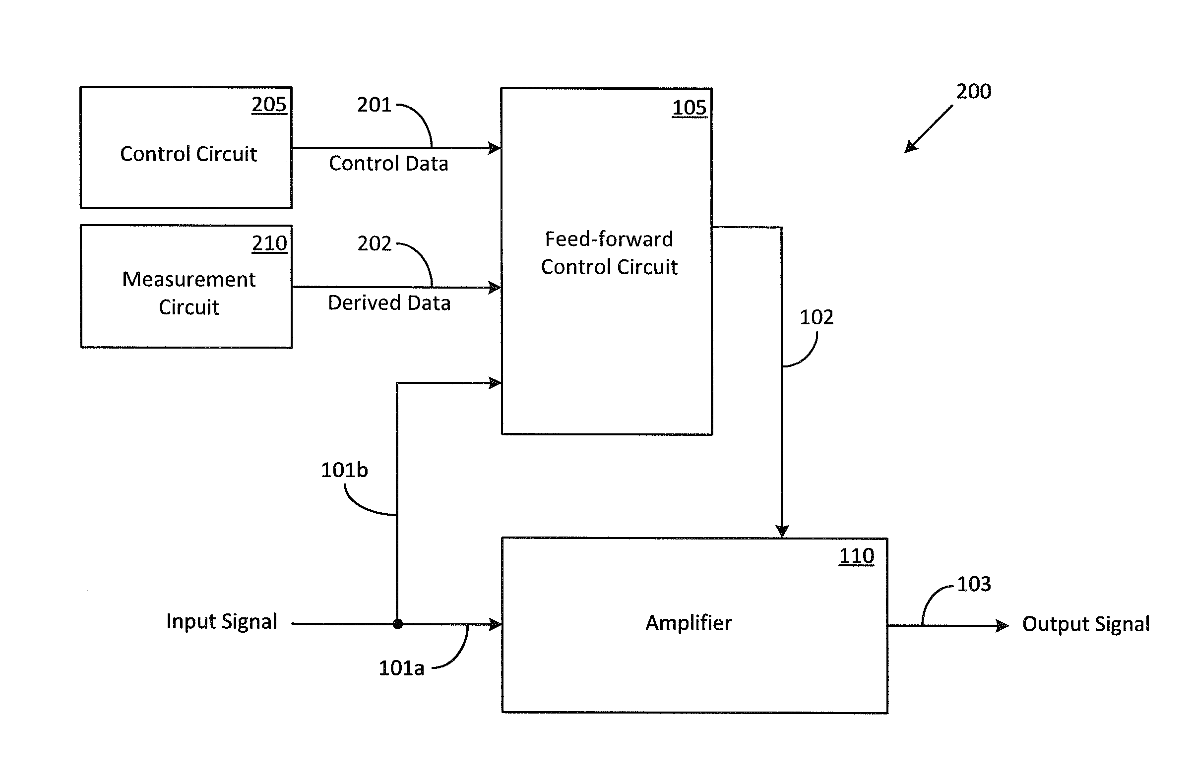
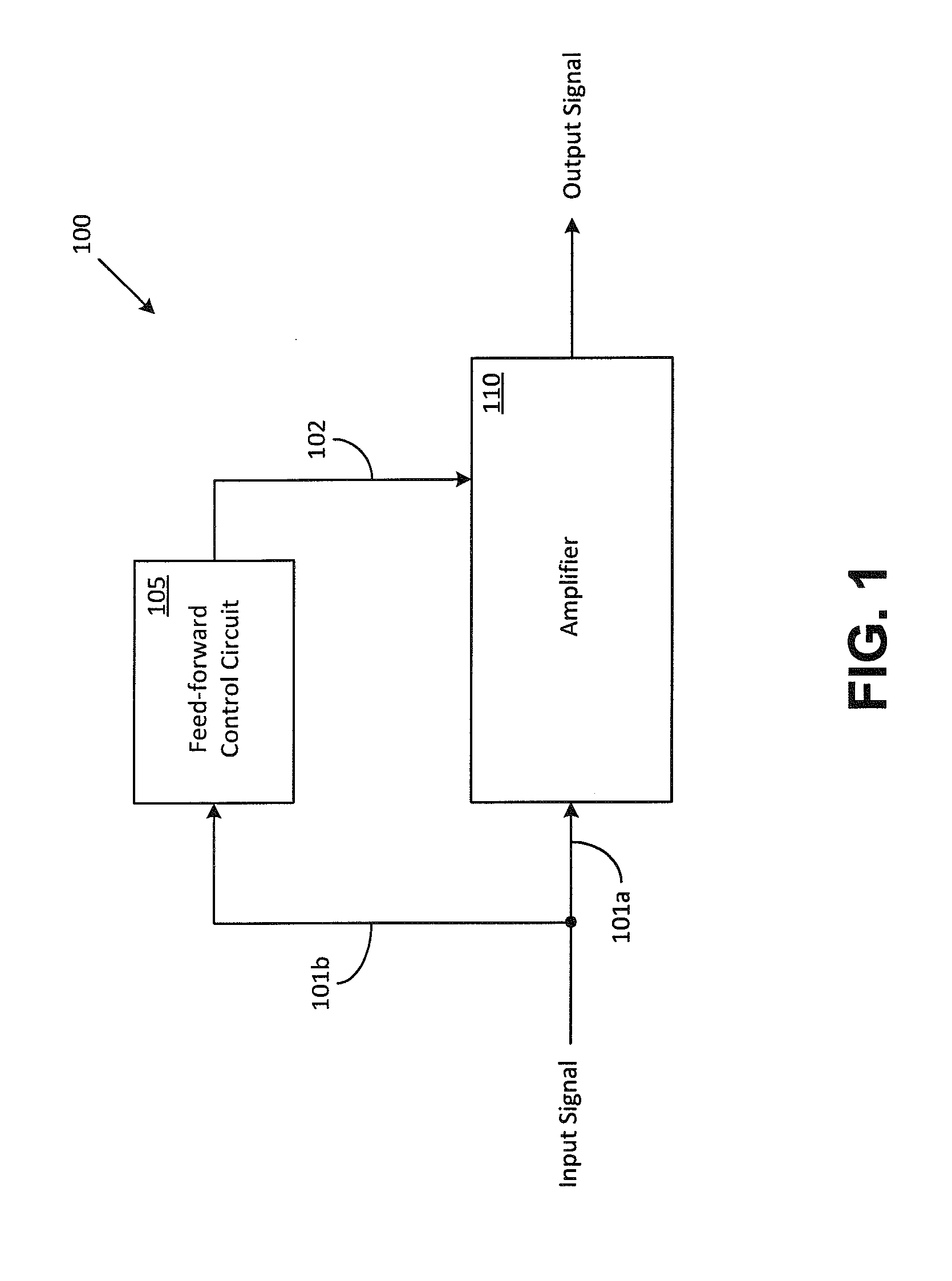
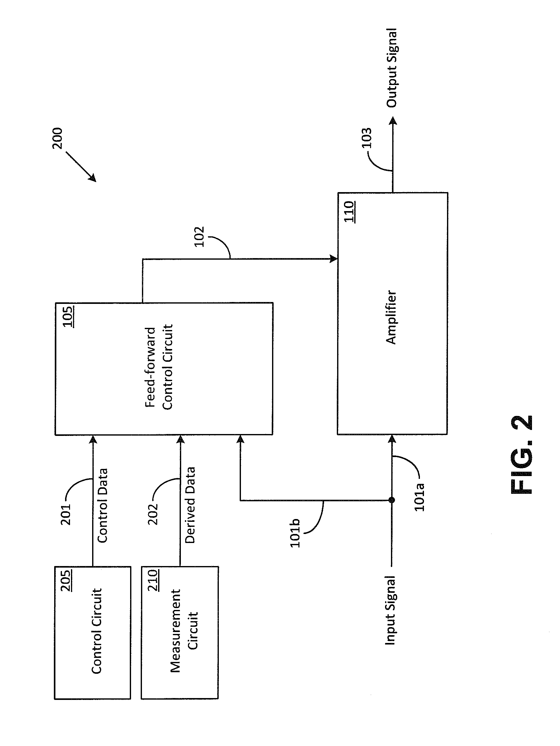
[0015]Throughout this description, embodiments and variations are described for the purpose of illustrating uses and implementations of the inventive concept. The illustrative description should be understood as presenting examples of the inventive concept, rather than as limiting the scope of the concept as disclosed herein. For example, it will be understood that terminology such as nodes, terminals, voltage drops, circuits, blocks, connections, lines, and coupling are used herein as a matter of convenience for description purposes and should not be interpreted literally in a narrow sense. Furthermore, the words “block” or “functional blocks” as used herein refer not only to a circuit containing discrete components or integrated circuits (ICs), but may also refer to various other elements such as a module, a sub-module, or a mechanical assembly. Similarly, the word “line” as used herein may refer to various connectivity elements such as a wire, a cable, a copper track on a printed...


PUM


Abstract

Methods and systems for optimizing amplifier operations are described. The described methods and systems particularly describe a feed-forward control circuit that may also be used as a feed-back control circuit in certain applications. The feed-forward control circuit provides a control signal that may be used to configure an amplifier in a variety of ways.

Description

1. FIELD[0001]The present teachings relate to amplifiers. In particular, the present teachings relate to optimizing amplifier operation by providing a feed-forward control signal that is used to affect amplifier operation in one or more ways.2. DESCRIPTION OF RELATED ART[0002]Amplifier gain is typically maintained over a range of operating conditions by using a feedback control circuit. For example, the feedback control circuit monitors the amplitude of an output signal of the amplifier and detects any variation of this amplitude from a nominal value. Based on the detected variation, the feedback control circuit generates a feedback control signal that is applied back upon the amplifier (input) so as to either increase, or to decrease the amplifier gain and bring the output signal of the amplifier to the nominal value. However, this gain feedback operation may result in adversely impacting the output signal, for example the control loop may be too slow or may become unstable. Furthe...

Claims


Application Information

Patent Timeline
Patent Type & Authority Applications(United States)
IPC IPC(8): H03F1/32
CPCH03F1/3223H03F1/30H03F3/195H03F3/72H03F2200/105H03F2200/468H03F1/0205H03F3/193H03F2200/324H03F2200/387H03F2200/451H03G3/3036
Inventor NOBBE, DAN WILLIAMHALCHIN, DAVID
Owner PSEMI CORP
Why Eureka
Try Eureka