Power management integrated circuit partitioning with dedicated primary side control winding

a technology of integrated circuit and primary side control, applied in the direction of power conversion system, dc-dc conversion, climate sustainability, etc., can solve the problems of irreparable damage, and inability to fully realize the effect of optical coupler circui

Active Publication Date: 2014-09-18
FLEXTRONICS AP LLC
View PDF4 Cites 33 Cited by
  • Summary
  • Abstract
  • Description
  • Claims
  • Application Information

AI Technical Summary

Benefits of technology

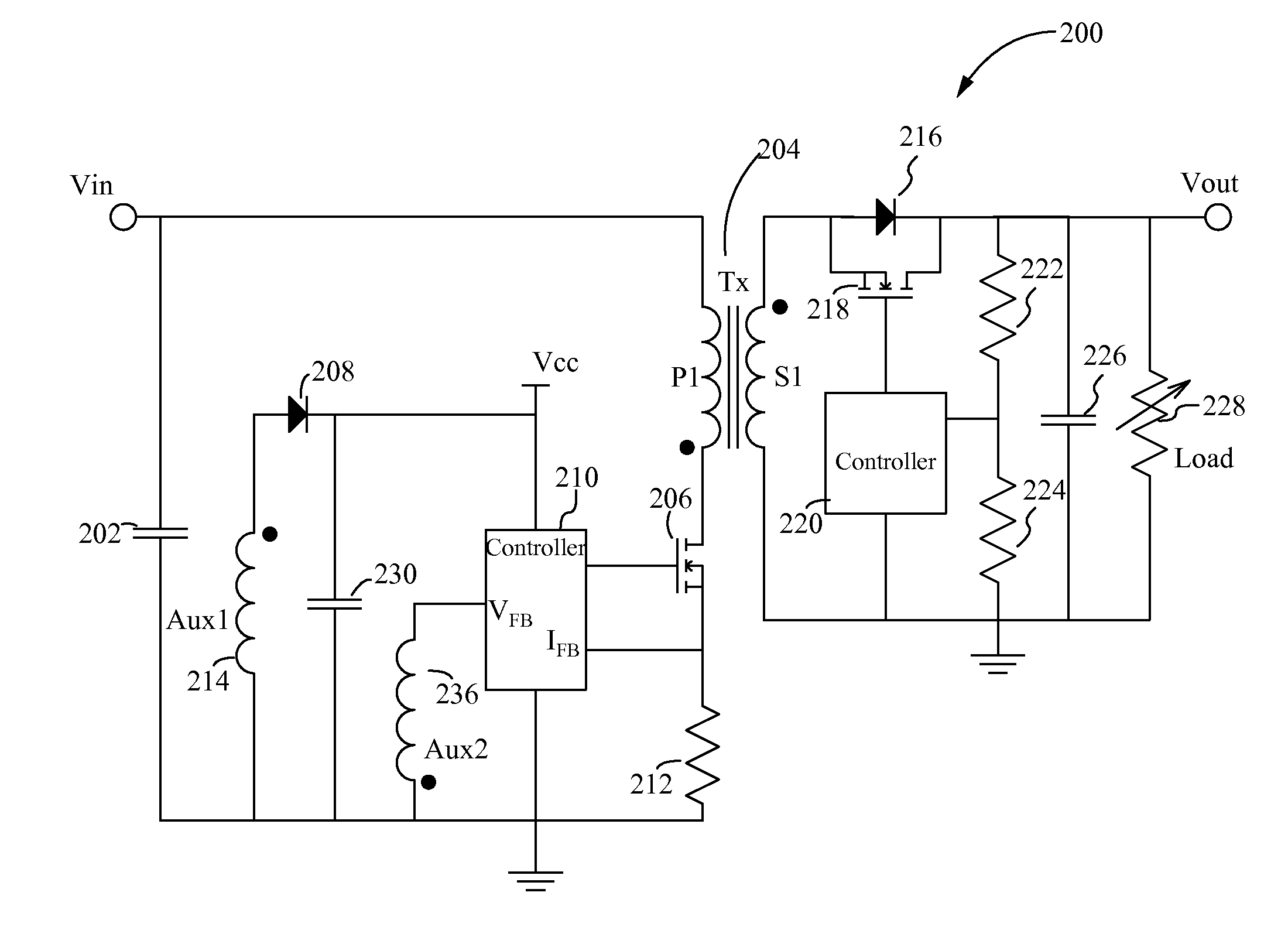
[0015]Embodiments of a switched mode power converter are directed to a feedback mechanism by which a coded train of pulses with well defined integrity is generated on a secondary side of the power converter and transmitted to a dedicated control signal winding on the primary side for decoding and application to regulate the power converter output. The control signal winding enables separation of control signal transmission and power transmission resulting in improved processing of the control signal by a primary side controller. The pulse train is modulated by a secondary side controller, transmitted across a transformer and received by the control signal winding, and supplied to the primary side controller. Such a technique allows the transmission of regulation data over an isolation galvanic barrier without using an optical coupling circuit. Coded information is included in the coded pulse train by modulating pulses of the pulse train including, but no limited to, the pulse width, the pulse amplitude, the pulse frequency, or any combination thereof.
[0016]In an aspect, a switching mode power converter is configured for forward energy transfer from a primary side to a secondary side and for reverse energy transfer from the secondary side to the primary side. The power converter includes a transformer, a first switch, a first controller, a second switch, a second controller, a first auxiliary winding and a second auxiliary winding. The Transformer has a primary winding coupled to an input supply voltage and a secondary winding. The first switch is coupled in series to the primary winding. The first controller is coupled to the switch, and the first controller is configured to turn the first switch ON and OFF. The second switch is coupled in series to the secondary winding. The second controller is coupled to the second switch, and the second controller is configured to turn the second switch ON and OFF thereby controlling a negative current through the secondary winding. The first auxiliary winding is electrically coupled to the first controller and magnetically coupled to the secondary winding to receive a power component of the reverse energy transfer for providing power to the first controller. The second auxiliary winding is electrically coupled to the first controller and magnetically coupled to the secondary winding to receive a control component of the reverse energy transfer for providing a feedback signal to regulate a circuit output characteristic.
[0017]In some embodiments, the second controller is configured to drive the second switch to generate negative current through the secondary winding to form a coded control signal, further wherein the transformer is configured as a signal transmitter to transmit the coded control signal from the secondary side of the transformer to the primary side of the transformer, wherein the first controller is configured to decode the coded control signal to identify the control information, generate a driving signal according to the control information, and drive the first switch using the driving signal to regulate an output characteristic. In some embodiments, the coded control signal is a pulse train signal having a modulated plurality of voltage pulses. The modulated plurality of pulses can be modulated by modulating one or more of a pulse amplitude, a pulse frequency, a pulse width, a pulse delay, and a number of pulse cycles. The second controller is configured to transmit the coded control signal during an OFF period of the first switch. The output characteristic can be one or more of an output voltage, an output current, and an output power of the power converter. The power converter can also include a sensing circuit coupled to the secondary winding and the second controller, wherein the sensing circuit is configured to sense the output characteristic of the power converter. In some embodiments, the first auxiliary winding has a same polarity as the secondary winding, and the second auxiliary winding has an opposite polarity of the secondary winding. In some embodiments, the forward energy transfer from the primary side of the transformer to the secondary side of the transformer does not induce current in the second auxiliary winding. In some embodiments, first switch is a first transistor and the second switch is a second transistor. The power converter can also include a diode coupled in parallel to the second switch and an output capacitor coupled in series to the diode, wherein the diode is configured to enable current flow from the secondary winding to the output capacitor when forward-biased. In this configuration, when the second switch is ON, an alternative current path through the second switch is formed between the output capacitor and the secondary winding of the transformer, further wherein a negative secondary current flows from the output capacitor to the secondary winding via the alternative current path. In some embodiments, the second auxiliary winding is configured to provide a sampling signal used for control by the first controller, the sampling signal is provided when the first switch is ON and OFF.
[0018]In another aspect, a method of controlling a switching mode power converter is disclosed. The method includes configuring a switching mode power converter. The power converter includes a transformer, a first switch, a first controller, a second switch, a second controller, a first auxiliary winding and a second auxiliary winding. The transformer has a primary winding coupled to an input supply voltage and a secondary winding. The first switch is coupled in series to the primary winding. The first controller is coupled to the switch. The second switch is coupled in series to the secondary winding. The second controller is coupled to the second switch. The first auxiliary winding is electrically coupled to the first controller and magnetically coupled to the secondary winding. The second auxiliary winding is electrically coupled to the first controller and magnetically coupled to the secondary winding. The first auxiliary winding is dedicated to receive a power transmission for powering the first controller. The second auxiliary winding is dedicated to receive a coded control signal for controlling the first switch. The method also includes driving the second switch by the second controller to generate the coded control signal, and transmitting the coded control signal from the secondary winding to the second auxiliary winding. The method also includes decoding the coded control signal by the first controller to identify control information, and driving the first switch using a driving signal generated according to the control information.
[0019]In some embodiments, the first auxiliary winding has a same polarity as the secondary winding, and the second auxiliary winding has an opposite polarity as the secondary winding. In some embodiments, a forward energy transfer from the primary side of the transformer to the secondary side of the transformer does not induce current in the second auxiliary winding. In some embodiments, driving the second switch generates negative current through the secondary winding to form the coded control signal. In some embodiments, the coded control signal comprises a pulse train signal having a modulated plurality of voltage pulses. The modulated plurality of pulses can be modulated by modulating one or more of a pulse amplitude, a pulse frequency, a pulse width, a pulse delay, and a number of pulse cycles. The coded control signal is transmitted during an OFF period of the first switch. The method can also include measuring an output characteristic of the secondary side of the transformer and the coded control signal is generated according to the output characteristic. The output characteristic can be one or more of an output voltage, an output current, and an output power of the power converter. In some embodiments, generating the coded control signal includes generating and applying a driving signal to the second switch to turn the second switch ON and OFF according to a determined pattern resulting in a modulated plurality of voltage pulses across the secondary winding of the transformer. In some embodiments, turning the second switch ON enables a negative secondary current through the secondary winding. In some embodiments, enabling the negative secondary current includes enabling an alternative current path from an output capacitor in the output circuit to the secondary winding. In some embodiments, the second auxiliary winding provides a sampling signal used for control by the first controller, the sampling signal is provided when the first switch is ON and OFF.

Problems solved by technology

Some circuits are subject to uncertain and undesirable functioning and even irreparable damage if supplied power falls outside a certain range.
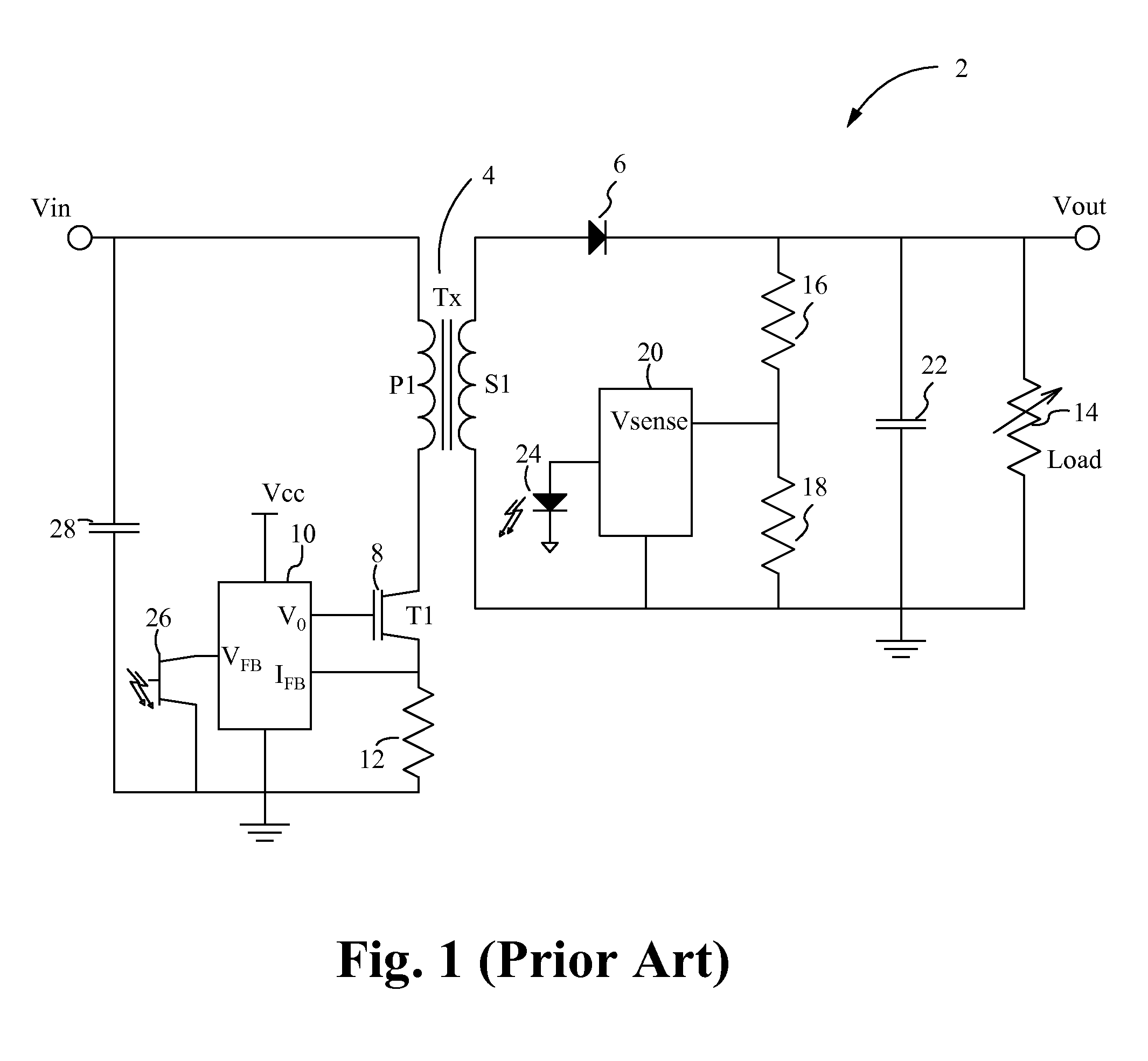
However, the use of an optical coupler circuit in and of itself presents issues.
Firstly, the optical coupler circuit adds extra cost.
In some applications, the optical coupler circuit can add more cost to the power converter than the isolation transformer.
The optical coupler circuit also adds to manufacturing and testing costs.
Furthermore, the performance of the optical coupler circuit degrades over time and therefore introduces another potential point of failure in the overall power converter.
The optical coupler circuit also has delays related to the operation of the optical diode and the optical transistor, and the operation of the optical diode requires a well defined DC level.
The waveform analyzer of FIG. 3 is limited to signal processing in DC or real-time switching waveforms.
For at least these reasons, providing a pulse with sufficient pulse integrity is often difficult to achieve.

Method used


Image

  • Power management integrated circuit partitioning with dedicated primary side control winding
  • Power management integrated circuit partitioning with dedicated primary side control winding
  • Power management integrated circuit partitioning with dedicated primary side control winding

Examples


Embodiment Construction

[0029]Embodiments of the present application are directed to a power converter. Those of ordinary skill in the art will realize that the following detailed description of the power converter is illustrative only and is not intended to be in any way limiting. Other embodiments of the power converter will readily suggest themselves to such skilled persons having the benefit of this disclosure.

[0030]Reference will now be made in detail to implementations of the power converter as illustrated in the accompanying drawings. The same reference indicators will be used throughout the drawings and the following detailed description to refer to the same or like parts. In the interest of clarity, not all of the routine features of the implementations described herein are shown and described. It will, of course, be appreciated that in the development of any such actual implementation, numerous implementation-specific decisions must be made in order to achieve the developer's specific goals, such...


PUM


Abstract

A switched mode power converter having a feedback mechanism by which a coded train of pulses with well defined integrity is generated on a secondary side of the power converter and transmitted to a dedicated control signal winding on the primary side for decoding and application to regulate the power converter output. The control signal winding enables separation of control signal transmission and power transmission resulting in improved processing of the control signal by a primary side controller. The pulse train is modulated by a secondary side controller, transmitted across a transformer and received by the control signal winding, and supplied to the primary side controller. Coded information is included in the coded pulse train by modulating pulses of the pulse train.

Description

RELATED APPLICATIONS[0001]This patent application claims priority under 35 U.S.C. 119 (e) of the co-pending U.S. Provisional Application Ser. No. 61 / 799,124, filed Mar. 15, 2013, and entitled “New Power Management Integrated Circuit Partitioning With Dedicated Primary Side Control Winding” and the co-pending U.S. Provisional Application Ser. No. 61 / 793,099, filed Mar. 15, 2013, and entitled “New Power Management Integrated Circuit Partitioning”. This application incorporates U.S. Provisional Application Ser. No. 61 / 799,124 and U.S. Provisional Application Ser. No. 61 / 793,099 in their entireties by reference.FIELD OF THE INVENTION[0002]The present invention is generally directed to the field of power converters. More specifically, the present invention is directed to controlling a power converter.BACKGROUND OF THE INVENTION[0003]In many applications a power converter is required to provide a voltage within a predetermined range formed from a voltage source having a different voltage ...

Claims


Application Information

Patent Timeline
Patent Type & Authority Applications(United States)
IPC IPC(8): H02M3/335
CPCH02M3/33592H02M3/33523H02M3/33515Y02B70/10
Inventor TELEFUS, MARK
Owner FLEXTRONICS AP LLC
Why Eureka
Try Eureka