
Pump having an automated gas removal and fluid recovery system and method

a technology of gas removal and fluid recovery system, applied in the direction of program control, separation process, instruments, etc., can solve the problems of corrosion, toxic and expensive, and defects in the very small structure formed during such processes, and the purity of the process fluid is often critical, and the defect of the very small structure is often critical

Active Publication Date: 2014-09-18
TELEDYNE DIGITAL IMAGING US INC
View PDF6 Cites 17 Cited by
  • Summary
  • Abstract
  • Description
  • Claims
  • Application Information

AI Technical Summary

Benefits of technology

The patent describes an automated pump system for removing gas from a process fluid to be dispensed. The system includes a process fluid reservoir, a driving means, valves, a sensor, and a processor. The sensor provides a signal indicating the presence of gas in the process fluid reservoir, and the processor uses this signal to automatically control the valves and driving means. The system removes any gas in the process fluid reservoir and filters out any particulate matter, resulting in a process fluid with no gas therein. The system can be used in various applications where the removal of gas is necessary.

Problems solved by technology

Many of the chemicals used in manufacturing integrated circuits, photomasks, and other devices with very small structures are corrosive, toxic and expensive.
Furthermore, purity of the process fluid is often critical.
Even the smallest foreign particles contaminating a process fluid cause defects in the very small structures formed during such processes.
Improper handling can also result in introduction of gas bubbles and damage the chemistry.
Depending on the design of the pump, this tends to be cumbersome and expensive, or simply not feasible.

Method used


Image

  • Pump having an automated gas removal and fluid recovery system and method
  • Pump having an automated gas removal and fluid recovery system and method
  • Pump having an automated gas removal and fluid recovery system and method

Examples


Embodiment Construction

[0076]The invention will be illustrated in more detail with reference to the following embodiments, but it should be understood that the present invention is not deemed to be limited thereto.

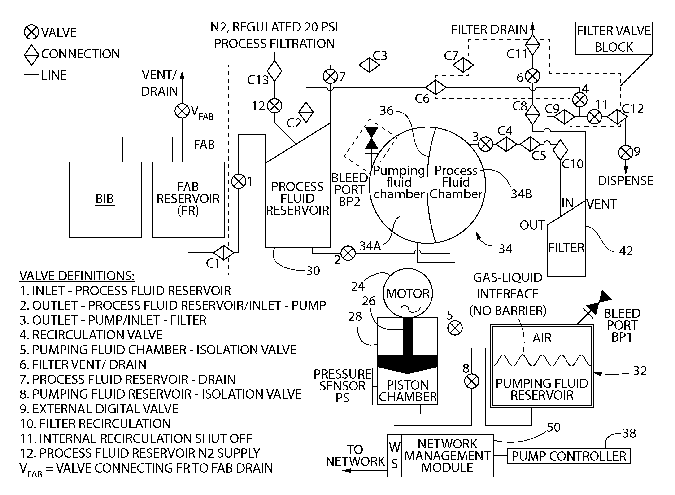
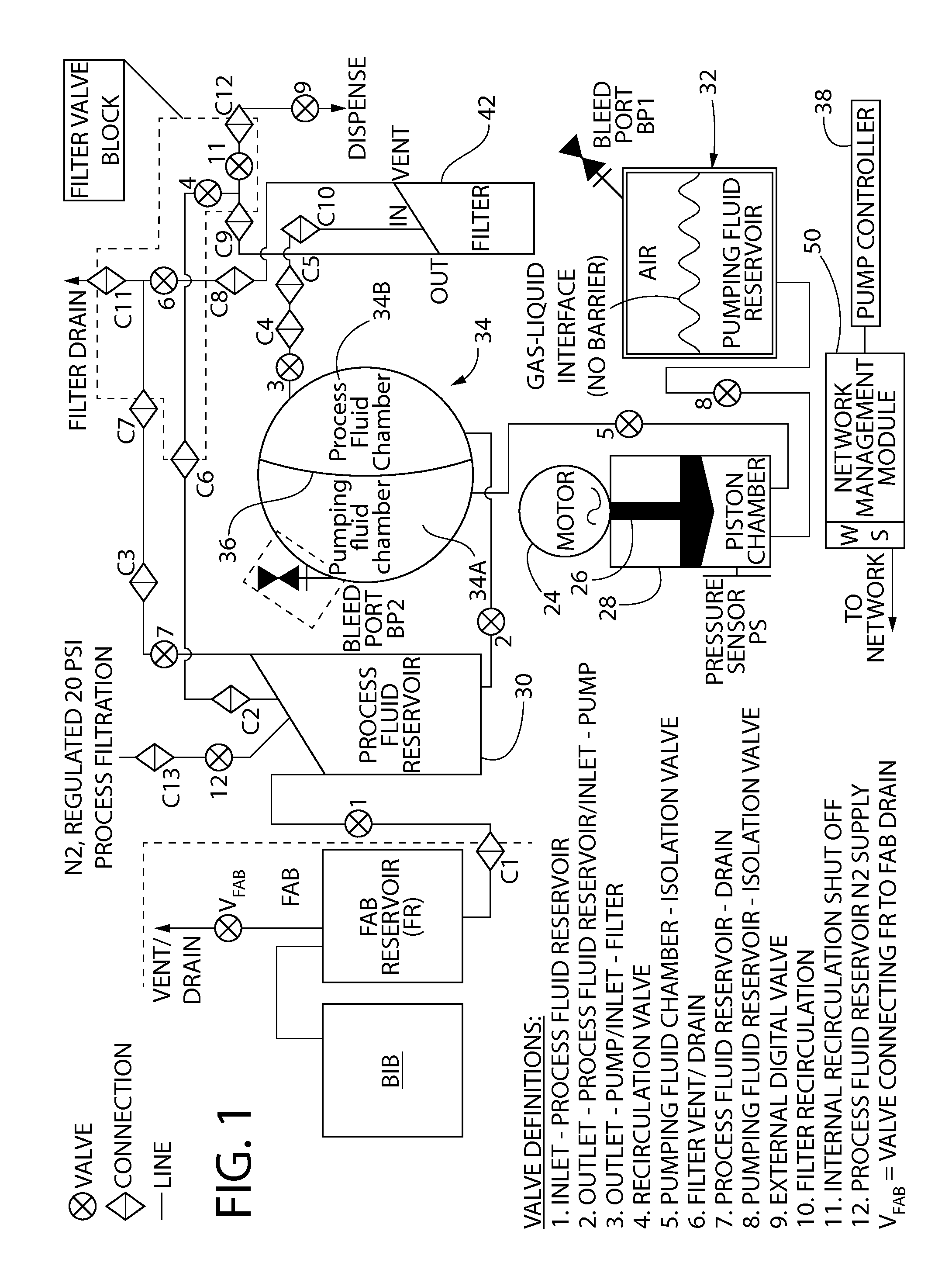
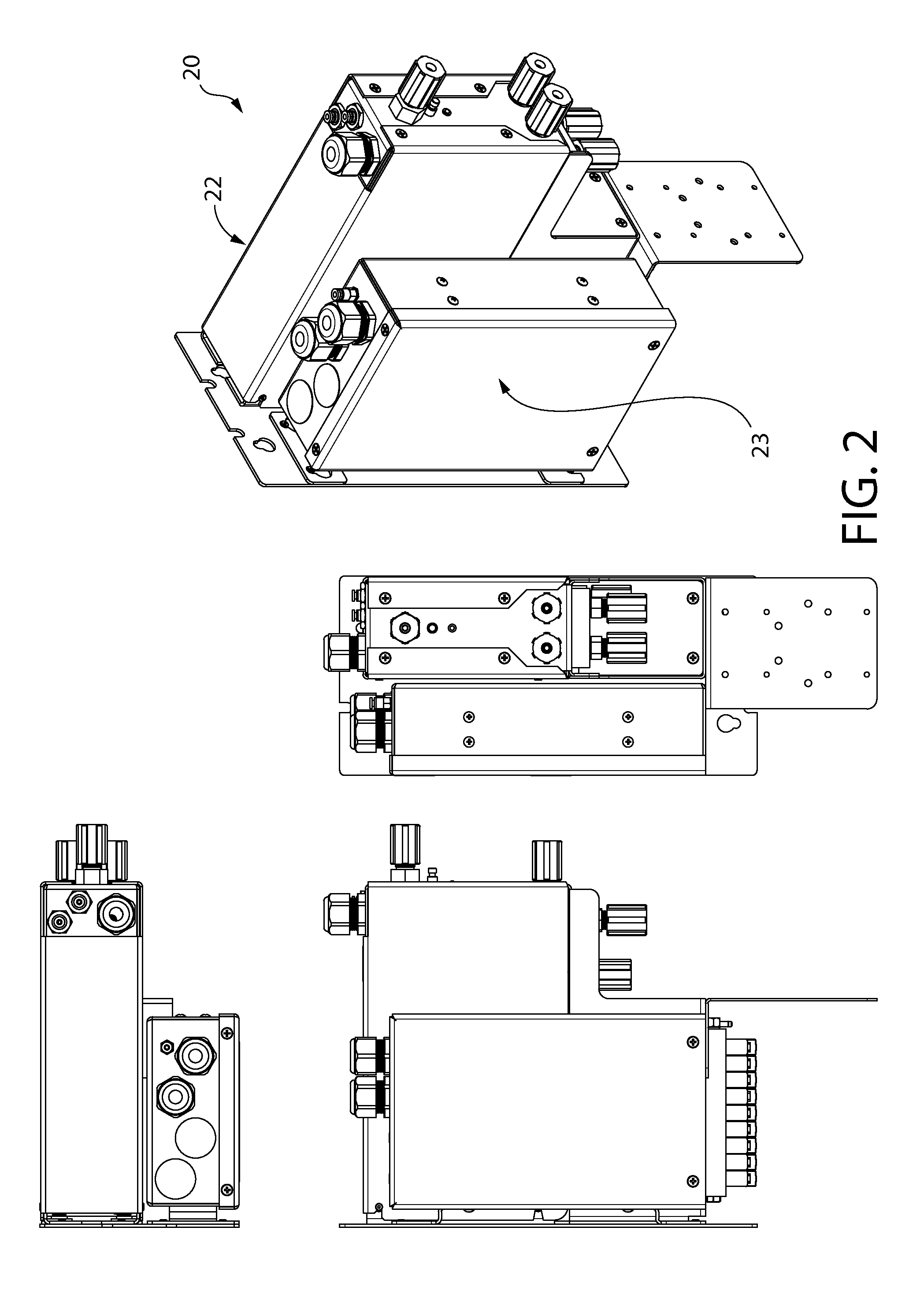
[0077]Referring now to the drawings, wherein like part numbers refer to like elements throughout the several views, there is shown a block diagram of an exemplary embodiment of the present invention 20 that uses a precision pump system. The present invention 20 may form a portion of an integrated circuit wafer fabrication process, by way of example only, for dispensing a precise amount of process fluid to the wafer fabrication. As shown in FIG. 1, the present invention 20 is coupled to fabrication equipment, e.g., a fabrication reservoir FR which in turn is connected to a BIB (“bag in bottle” which supplies process fluid to the fabrication reservoir); a vent / drain is connected to the fabrication reservoir FR via a valve, VFAB.

[0078]As shown in FIGS. 1-2, the present invention 20 comprises a prec...


PUM

PropertyMeasurementUnit
pressureaaaaaaaaaa
pressureaaaaaaaaaa
volumeaaaaaaaaaa

Abstract

A precision pump system having a motor driver for accurately and repeatedly delivering process fluid, (e.g., photo chemicals) using a pumping fluid with minimal process fluid loss to a fabrication process and whereby the motor driver can be easily and quickly replaced without interrupting the fluid flow path. This is accomplished with the use of a process fluid reservoir and a pumping fluid reservoir that are associated with the pump, either integrated with the pump or closely adjacent. In addition, this precision pump system can be remotely monitored, viewed and controlled over the Internet. In addition, trapped process fluid within a downstream filtering block can be recirculated to the process fluid reservoir when trapped gas in the filter is removed. Furthermore, a nitrogen gas source is connected to the process fluid reservoir via a valve in case a need to insert a gas is required.

Description

CROSS-REFERENCE TO RELATED APPLICATIONS[0001]This international application claims the benefit under 35 U.S.C. §119(e) of Provisional Application Ser. No. 61 / 789,217 filed on Mar. 15, 2013 entitled PUMP HAVING A QUICK CHANGE MOTOR DRIVE SYSTEM and whose entire disclosure is incorporated by reference herein.BACKGROUND OF THE INVENTION[0002]The present invention relates generally to apparatus used in metering fluids with high precision, particularly in fields such as semiconductor manufacturing.[0003]Many of the chemicals used in manufacturing integrated circuits, photomasks, and other devices with very small structures are corrosive, toxic and expensive. One example is photoresist, which is used in photolithographic processes. In such applications, both the rate and amount of a chemical in liquid phase—also referred to as process fluid or “chemistry”—that is dispensed onto a substrate must be very accurately controlled to ensure uniform application of the chemical and to avoid waste ...

Claims


Application Information

Patent Timeline
Patent Type & Authority Applications(United States)
IPC IPC(8): F04B49/22F04B43/04F04B53/06F04B17/03
CPCF04B49/22F04B53/06F04B43/04F04B17/03F04B49/10F04B13/00F04B53/22Y10T29/49236F04B43/073F04B43/067F04B35/04G05B19/048F04B43/107F04B43/113F04B35/00B01D19/0063B01D19/0073
Inventor VINES, JOHN C.LAESSLE, JOHN
Owner TELEDYNE DIGITAL IMAGING US INC
Learn More