High frequency mixer, method and system

Inactive Publication Date: 2014-09-18
L 3 COMM CORP
View PDF6 Cites 7 Cited by
  • Summary
  • Abstract
  • Description
  • Claims
  • Application Information

AI Technical Summary

Benefits of technology

[0017]According to one of the embodiments, the circuit is of thin-film construction which possesses a multilayer structure. This embodiment has a support substrate, with no air gap below it. The mixing elements may be built all on the top side of the substrate without cavities beneath the substrate. The signal paths created for each signal in the circuit are chosen such that the circuit achieves maximum attenuation of the undesired harmonics of the LO sour

Problems solved by technology

Typically these other frequency outputs are unwanted, and serve only as noise or interference.
However, in the example, the two frequencies are so close that to try to filter out the 2×LO spur and pass the IF signal is difficult.
In addition, the use of one or more filters of this type ha

Method used


Image

  • High frequency mixer, method and system
  • High frequency mixer, method and system
  • High frequency mixer, method and system

Examples


Embodiment Construction

[0025]For the purposes of promoting and understanding the principles disclosed herein, reference is now made to the preferred embodiments illustrated in the drawings.

[0026]The lightweight mixer design described here is particularly applicable to circuitry used in satellites to process high-frequency wireless radio signals. Weight is a particular concern in orbital devices, due to the high cost of launch based on weight. An exemplary system is therefore shown herein on a satellite, although it will be understood that the invention may have a wide range of terrestrial uses as well.

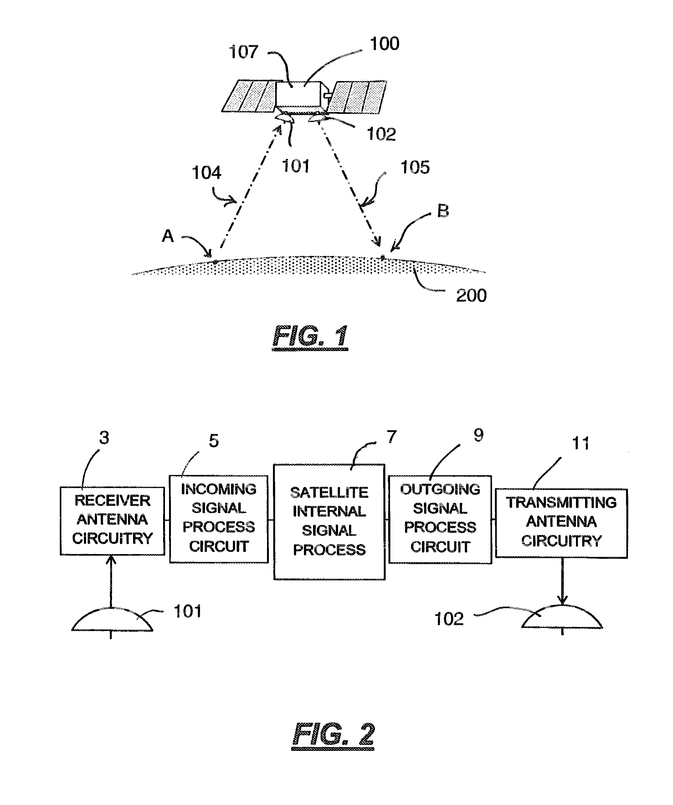
[0027]Referring to FIG. 1, a satellite 100 is shown in orbit above the Earth 200 (or potentially some other celestial body). The satellite 100 is provided with antennae 101 and 102. According to the embodiment shown, antenna 101 receives one or more wireless radio signals indicated generally at 104 from an earth station indicated at A. These radio signals are normally high-frequency RF signals, i.e., with a ...


PUM


Abstract

A thin film circuit, particularly desirable for satellite communications, mixes RF and an LO giga-hertz-range input signals to yield an IF signal by splitting the LO and RF signals into two, with a 180 degree phase shift introduced into one of the resulting signals. The LO and RF signals are then each mixed in parallel mixers. The outputs of the mixers have the IF signal with spurious (spur) signals in frequencies that are multiples of the frequencies of the RF or LO signals. The outputs are mixed together so that some of the spur signals cancel each other out and the IF signals are added in phase.

Description

FIELD OF THE INVENTION[0001]The invention relates generally to radio transmitters utilizing a mixer to produce an output signal of a given frequency. In particular, the invention relates to circuits containing mixers that combine a first signal LO with a second signal RF to yield a third signal IF, especially in a relatively high-frequency application. More particularly, this invention relates to such circuits for use in satellites.BACKGROUND OF THE INVENTION[0002]A common way to combine two input signals to produce an output signal is to employ a mixer. A key feature of a mixer circuit is one or more mixing elements, which generally comprise a nonlinear device such as a diode, field effect transistor, or bipolar junction transistor.[0003]Mixing elements combine two frequency inputs to yield other frequency outputs, which vary according to the features of the particular mixing elements. In particular, mixing elements are designed to output second order frequencies, which include the...

Claims


Application Information

Patent Timeline
IPC IPC(8): H03D7/14H04B7/185
CPCH04B7/18513H03D7/1466H03D7/1408H03D7/1425H03D2200/0086
Inventor RALPH, LOREN EDWARDRODGERS, EDDIEMUIR, JEFFREY SCOT
Owner L 3 COMM CORP
Why Eureka
Try Eureka