Advanced valve actuator with integral energy metering

a valve actuator and energy meter technology, applied in the direction of instruments, heating types, static/dynamic balance measurement, etc., can solve the problems of time-consuming and costly efforts to monitor and manage energy consumption

Active Publication Date: 2014-09-18
SCHNEIDER ELECTRIC BUILDINGS AMERICAS INC
View PDF12 Cites 51 Cited by
  • Summary
  • Abstract
  • Description
  • Claims
  • Application Information

AI Technical Summary

Benefits of technology

[0006]In one aspect, embodiments of the invention provide an automatic control valve and actuator assembly that includes a valve configured to control a flow of fluid into a heat exchanger load or HVAC coil, and a valve actuator configured to control opening and closing of a self-actuated pressure-...

Problems solved by technology

However, this tends to make efforts to monitor and ...

Method used


Image

  • Advanced valve actuator with integral energy metering
  • Advanced valve actuator with integral energy metering
  • Advanced valve actuator with integral energy metering

Examples


Embodiment Construction

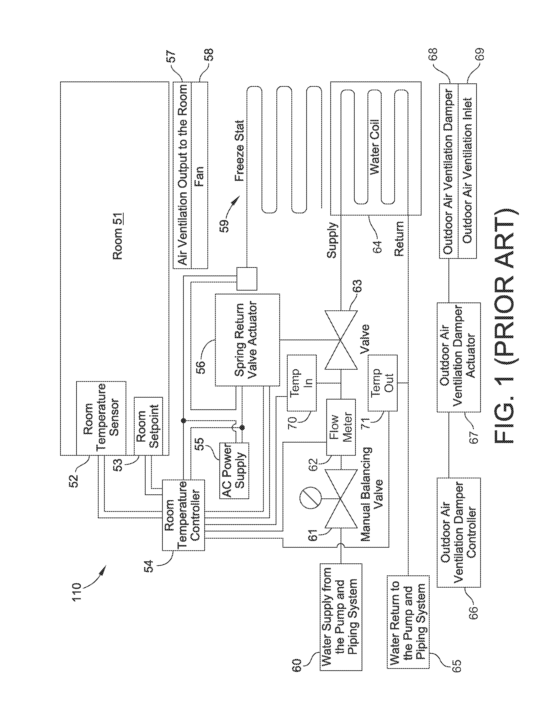
[0026]FIG. 1 is a schematic diagram showing a conventional HVAC system 110 that requires multiple devices to obtain the required water valve control and fluid flow and energy consumption calculation. The source of the hot and cold water for the water supply from the pump and piping system 60 is generally located outside of the room 51, and is usually a centralized supply consisting of one or more boilers or chillers (not shown) that can be alternately connected within the source. The valve 63 modulates the flow of hot and cold water from the water supply from the pump and piping system 60 for heating and / or cooling of the room 51. Typically, the valve 63 is mechanically driven by the spring return valve actuator 56 that is operatively connected in accordance with the control signal provided by the room temperature controller 54.

[0027]In typical embodiments, the room temperature controller 54 receives a temperature sensing signal from the room temperature sensor 52 and compares it to...


PUM


Abstract

An automatic control valve actuator assembly is configured to control opening and closing of the valve via positioning of a valve closure member. The valve actuator is further configured to determine the volume of fluid flowing through the valve. In an embodiment, the valve actuator includes an integral energy consumption calculation and retention module configured to calculate heat energy for energy consumption tracking.

Description

CROSS-REFERENCE TO RELATED PATENT APPLICATION[0001]This patent application claims the benefit of U.S. Provisional Patent Application No. 61 / 790,696, filed Mar. 15, 2013, the entire teachings and disclosure of which are incorporated herein by reference thereto.FIELD OF THE INVENTION[0002]This invention generally relates to valves and valve actuators and flow and energy meters, and more particularly, to valves and valve actuators and flow and energy meters configured to be controlled electronically with communications capability.BACKGROUND OF THE INVENTION[0003]Many types of commercial and industrial systems involve processes in which liquids are supplied via fluid control systems that may include a variety of both pumping assemblies and control valves. These fluid control systems include, but are not limited to, those used in electrical power stations, chemical manufacturing operations, food and beverage processing, liquid gas supply and disposal, water supply and disposal, heating, ...

Claims


Application Information

Patent Timeline
IPC IPC(8): F24F11/00G05B15/02
CPCG05B15/02F24F11/0086F24F11/30F24F2110/10F24F2140/12F24F11/84
Inventor BURT, ALAN
Owner SCHNEIDER ELECTRIC BUILDINGS AMERICAS INC
Why Eureka
Try Eureka