
Frame buffer access tracking via a sliding window in a unified virtual memory system

a frame buffer and memory system technology, applied in the field of computer science, can solve the problems of page fault generation, reducing the performance of the ppu, and limiting the types of tasks that the ppu can perform, so as to achieve the effect of increasing the overall performance of the memory subsystem

Active Publication Date: 2014-09-18
NVIDIA CORP
View PDF1 Cites 25 Cited by
  • Summary
  • Abstract
  • Description
  • Claims
  • Application Information

AI Technical Summary

Benefits of technology

The disclosed techniques describe a way to improve the performance of a memory system by using a sliding window tracker to select specific memory pages for migration between different memories. This approach improves overall performance better than randomly selecting pages and avoids the performance degradation that occurs with traditional fault-based access tracking techniques.

Problems solved by technology

However, the specialized design of these PPUs also limits the types of tasks that the PPU can perform.
However, since the OS may select a memory page that is subsequently accessed by the PPU for migration, such an approach may reduce the performance of the PPU.
If the PPU references a memory page included in this set of memory pages, then a page fault is generated.
While such an approach reduces the likelihood that the OS migrates memory pages that are subsequently accessed by the PPU, resolving the generated page faults degrades the overall performance of the computer system.
Additionally, setting a bit in the PTE generally requires a read-modify-write operation on the PTE, which is a significant overhead, because the performance path in the PPU memory management unit (PPU MMU) performs only read operations.
Consequently, this approach undesirably reduces the amount of PPU memory available for storage of application program data.

Method used


Image

  • Frame buffer access tracking via a sliding window in a unified virtual memory system
  • Frame buffer access tracking via a sliding window in a unified virtual memory system
  • Frame buffer access tracking via a sliding window in a unified virtual memory system

Examples


Embodiment Construction

[0019]In the following description, numerous specific details are set forth to provide a more thorough understanding of the present invention. However, it will be apparent to one of skill in the art that the present invention may be practiced without one or more of these specific details.

System Overview

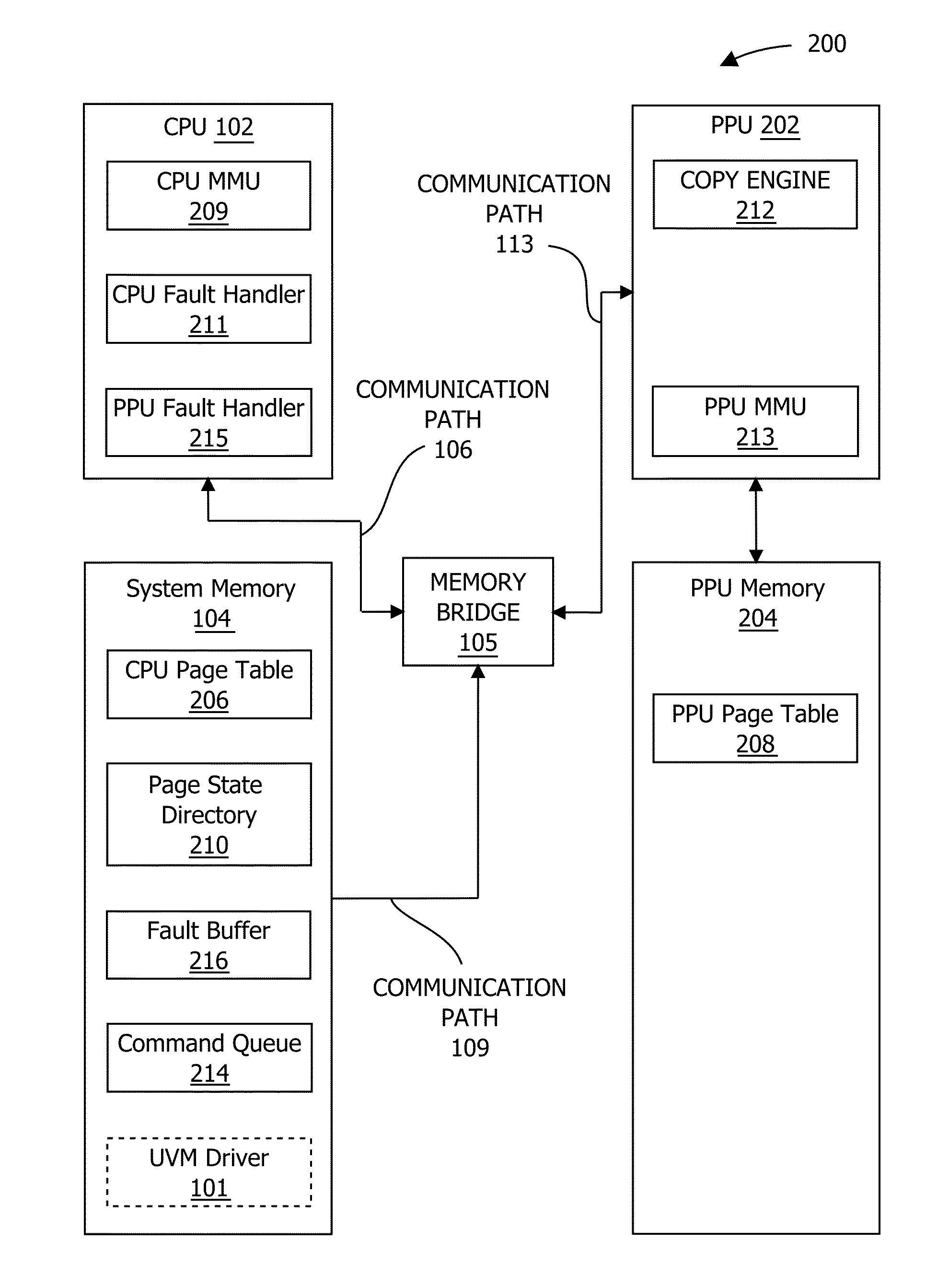
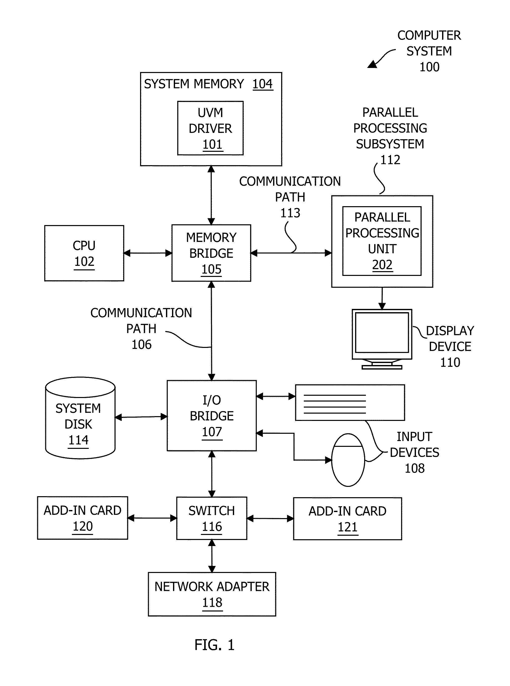
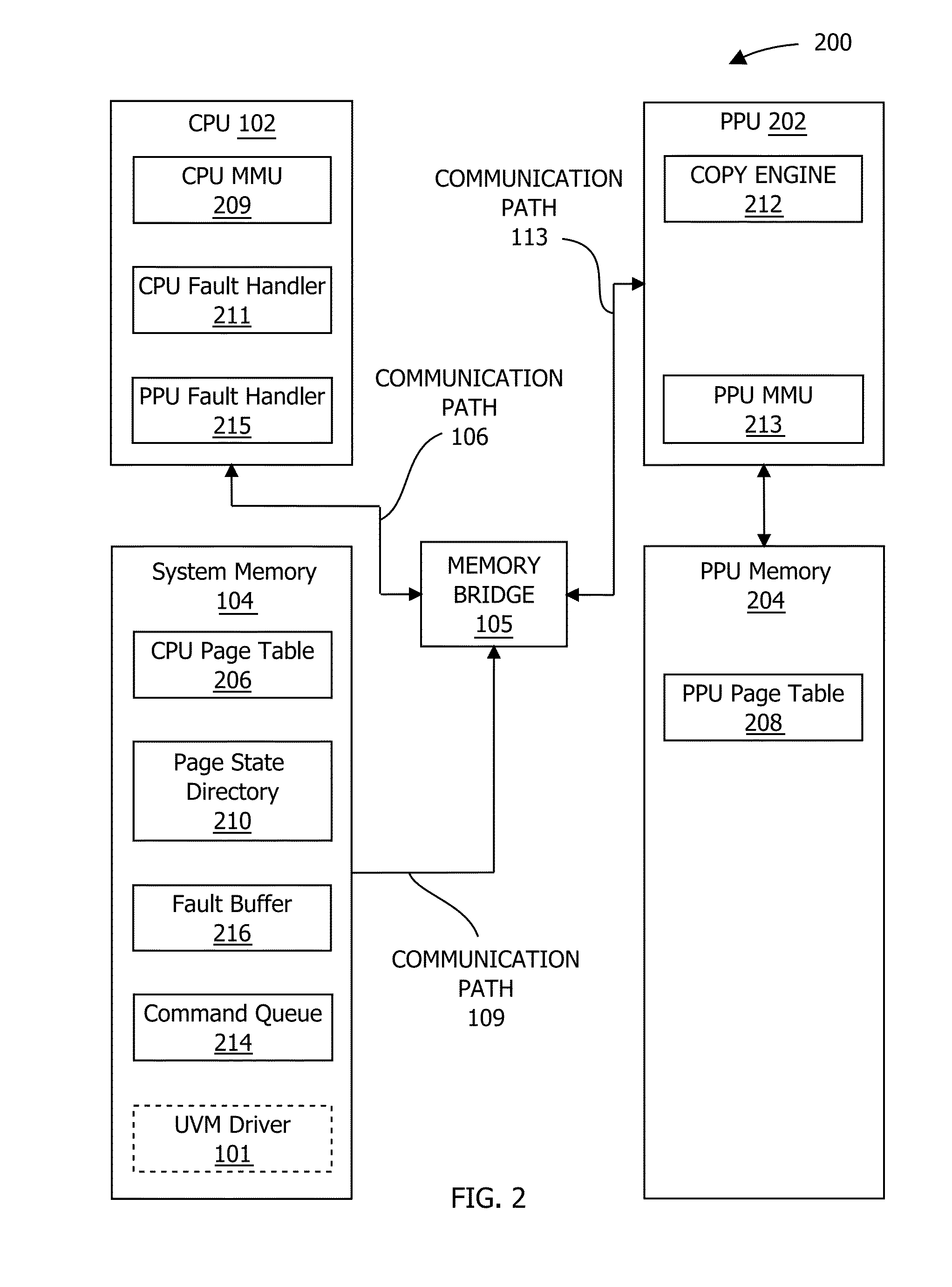
[0020]FIG. 1 is a block diagram illustrating a computer system 100 configured to implement one or more aspects of the present invention. Computer system 100 includes a central processing unit (CPU) 102 and a system memory 104 communicating via an interconnection path that may include a memory bridge 105. Memory bridge 105, which may be, e.g., a Northbridge chip, is connected via a bus or other communication path 106 (e.g., a HyperTransport link) to an I / O (input / output) bridge 107. I / O bridge 107, which may be, e.g., a Southbridge chip, receives user input from one or more user input devices 108 (e.g., keyboard, mouse) and forwards the input to CPU 102 via communication path 106 and m...


PUM


Abstract

One embodiment of the present invention is a memory subsystem that includes a sliding window tracker that tracks memory accesses associated with a sliding window of memory page groups. When the sliding window tracker detects an access operation associated with a memory page group within the sliding window, the sliding window tracker sets a reference bit that is associated with the memory page group and is included in a reference vector that represents accesses to the memory page groups within the sliding window. Based on the values of the reference bits, the sliding window tracker causes the selection a memory page in a memory page group that has fallen into disuse from a first memory to a second memory. Because the sliding window tracker tunes the memory pages that are resident in the first memory to reflect memory access patterns, the overall performance of the memory subsystem is improved.

Description

CROSS-REFERENCE TO RELATED APPLICATIONS[0001]This application claims benefit of the U.S. Provisional Patent Application having Ser. No. 61 / 800,004 and Attorney Docket Number NVDA / SC-12-0565-US0, filed on Mar. 15, 2013, which is hereby incorporated herein by reference. This application claims also benefit of the U.S. Provisional Patent Application having Ser. No. 61 / 785,735 and Attorney Docket Number NVDA / SC-12-0570-US0, filed on Mar. 14, 2013, which is hereby incorporated herein by reference.BACKGROUND OF THE INVENTION[0002]1. Field of the Invention[0003]The present invention generally relates to computer science and, more specifically, to frame buffer access tracking via a sliding window in a unified virtual memory system.[0004]2. Description of the Related Art[0005]A typical computer system includes a central processing unit (CPU) and a parallel processing unit (PPU). Some PPUs are capable of very high performance using a relatively large number of small, parallel execution thread...

Claims


Application Information

Patent Timeline
IPC IPC(8): G06F12/10
CPCG06F12/1027G06F12/1009G06F12/08G06F3/0622G06F3/0631G06F3/0647G06F3/0685G06F2212/656G06F2212/684
Inventor MASHEY, JOHNBUSCHARDT, CAMERONDEMING, JAMES LEROYDULUK, JR., JEROME F.FAHS, BRIAN
Owner NVIDIA CORP
Learn More