Common rail fuel injection system

a fuel injection system and common rail technology, applied in liquid fuel feeders, machines/engines, mechanical equipment, etc., can solve the problems of increasing the weight of devices, complex structure, and increasing the manufacturing cost, so as to reduce the exhaust amount of smoke, suppress the pressure pulsation, and reduce the amount of pressure drop

Inactive Publication Date: 2014-09-25
USUI KOKUSAI SANGYO KAISHA LTD +1
View PDF2 Cites 4 Cited by
  • Summary
  • Abstract
  • Description
  • Claims
  • Application Information

AI Technical Summary

Benefits of technology

[0021]According to the present invention, it is made possible to reduce an exhaust amount of smoke as compared with the conventional structure by suppressing pressure pulsation generated due to injection and reducing an pressure drop amount at an injection time to improve an average value of pressures during injection (hereinafter, referred to as “average injection pressure value).
[0022]Further, since reduction of a peak pressure acting on the injection pipe can be made possible, the reduction is advantageous regarding an internal pressure fatigue strength performance of the injection pipe, a set pressure to the common rail system can be raised, and an exhaust amount of smoke can be suppressed.

Problems solved by technology

Therefore, it is required to carefully select a fuel pipe material and adopt an expensive manufacturing process, so that rising of a manufacturing cost becomes essential.
H10-30521 and Japanese Patent Application Laid-Open No. 2000-161171 it is possible to suppress pressure fluctuation within an injector due to fuel injection and obtain an even injection pressure characteristic by increasing a pressure accumulation volume, but there is such a drawback that a structure for achieving such an effect is complicated, which results in increase in device weight.

Method used


Image

  • Common rail fuel injection system
  • Common rail fuel injection system
  • Common rail fuel injection system

Examples


example 1

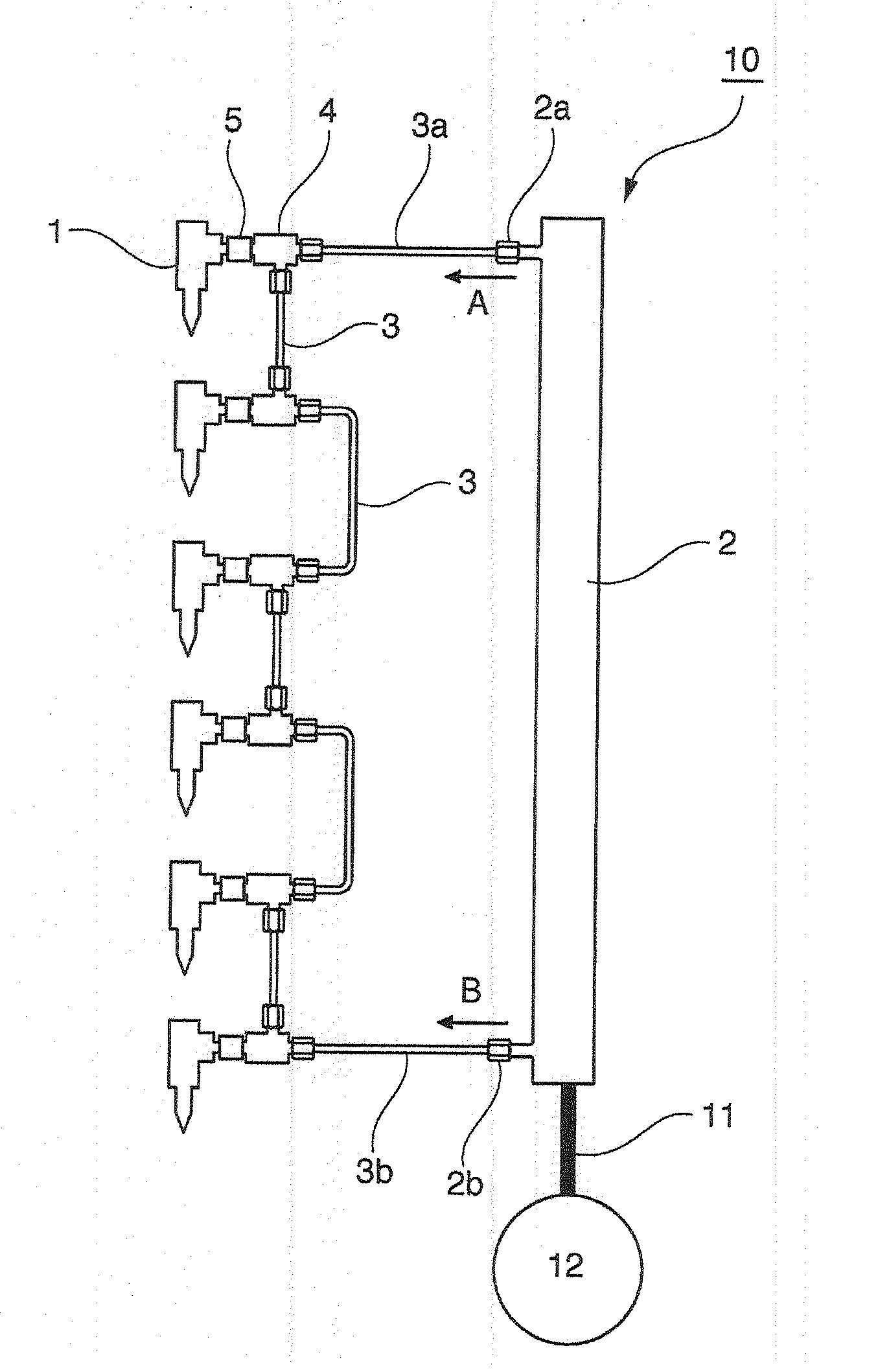
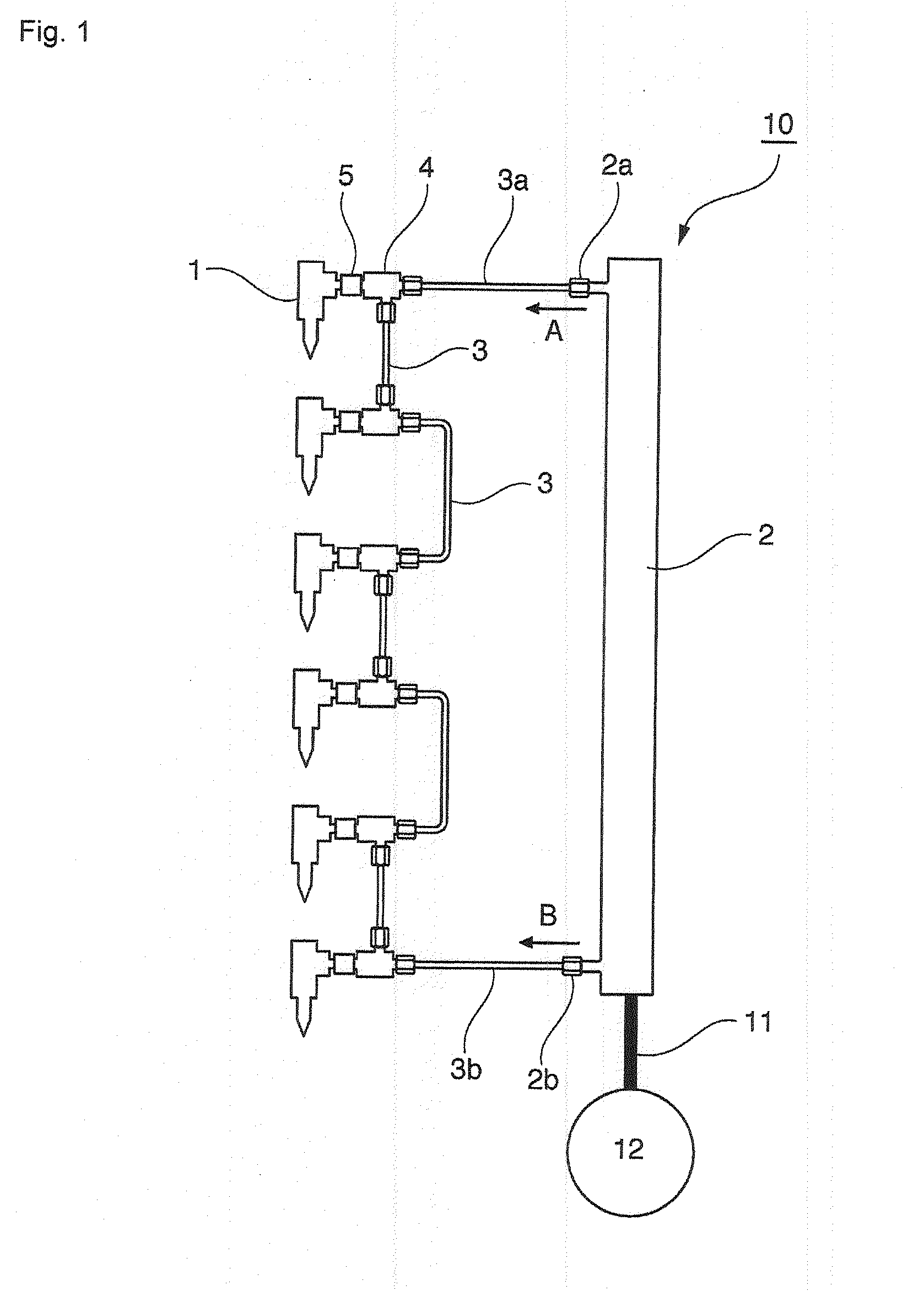
[0065]FIG. 7 is a schematic view of a fuel injection system 10a according to Example 1 (a case where same devices such as the fuel supply pipe and the high-pressure supply pump are used is not shown in the figures described below).

[0066]In FIG. 7, reference sign 1 denotes an injector; 2 denotes a common rail; 2a, 2b denotes a pressure supply port provided in the common rail 2; 3, 3a, 3b denotes a fuel injection pipe; 4 denotes a coupling connector; and 5 denotes a connection nut.

[0067]The fuel injection system 10a of Example 1 is one for a 6-cylinder diesel internal combustion engine, which has six injectors 1 (NI=6) and supplies high-pressure fuels to the six injectors 1 connected in series from the pressure supply ports 2a and 2b provided in the common rail 2 having two ports {(NP=2×(6 / 6))} through the fuel injection pipes 3a and 3b communicating with the pressure supply ports 2a and 2b, respectively.

[0068]In the fuel injection system 10a of Example 1, supply of fuel to each injec...

example 2

[0086]A schematic view of a fuel injection system 10b according to Example 2 is shown in FIG. 8.

[0087]The fuel injection system 10b of Example 2 is one for the same 6-cylinder diesel internal combustion engine as that of Example 1, Example 2 being the same as Example 1 such that the number NI of injectors 1 provided is also six, the number NP of pressure supply ports provided in the common rail 2 is also two (2a and 2b), and fuel where pressures in the fuel supply routes A and B of two lines have been averaged via each of coupling connectors 4 is supplied to a corresponding injector 1 to be injected into a corresponding cylinder.

[0088]A difference from Example 1 lies in a point that fuel is fed from each coupling connector 4 to a corresponding injector 1 via a fuel injection pipe 3. By feeding fuel via the fuel injection pipe 3, such a merit can be provided that the degree of freedom of arrangement of the fuel injection system within the engine room is increased.

example 3

[0089]A schematic view of a fuel injection system 10c according to Example 3 is shown in FIG. 9.

[0090]The fuel injection system 10c of Example 3 is one for the same 6-cylinder diesel internal combustion engine as those of Examples 1 and 2, Example 3 being the same as Examples 1 and 2 such that the number NI of injectors 1 provided is also six and the number NP of pressure supply ports provided in the common rail 2 is also two (2a and 2b), but it is a fuel injection system of a type where fuels from fuel supply routes A and B of two lines are directly fed to two fuel intake ports 6 and 6 provided in each injector 1 without interposition of any coupling connector as in Examples 1 and 2, averaging of fuel pressures within an injector 1 is performed, and injection into a corresponding cylinder is then performed.


PUM


Abstract

A common rail fuel injection system includes injectors having a fuel intake port and being provided for respective cylinders of a multi-cylinder diesel internal combustion engine, a common rail accumulating pressurized fuel, a high-pressure supply pump supplying high-pressure fuel, a fuel supply pipe causing the common rail and the high-pressure supply pump to communicate with each other. The fuel injection pipes communicating with pressure supply ports provided in the common rail and causing the injectors and the pressure supply ports to communicating with each other. The fuel injection pipes cause at least three injectors to communicate with one another in series. The number NP of pressure supply ports is less than the number PI of injectors, and supply of high-pressure fuel to the respective injectors for the cylinders is performed through fuel injection pipes of two lines.

Description

BACKGROUND[0001]1. Field of the Invention[0002]The present invention relates to a common rail fuel injection system for a diesel internal combustion engine, and more specifically to a common rail fuel injection system which is used in a diesel internal combustion engine and accumulates pressurized fuel in a common rail to inject the same into each cylinder.[0003]2. Description of the Related Art[0004]A common rail fuel injection system for a diesel internal combustion engine is a fuel injection system of an electromagnetic control type which accumulates high-pressure fuel in a common rail by a high-pressure supply pump to inject high-pressure fuel accumulated in the common rail into each cylinder, and a conventional common rail fuel injection system for a diesel internal combustion engine is shown in FIG. 28.[0005]The structure of the common rail fuel injection system is provided with an injector provided for each cylinder in a diesel internal combustion engine, a common rail for ac...

Claims


Application Information

Patent Timeline
Patent Type & Authority Applications(United States)
IPC IPC(8): F02M55/02
CPCF02M55/025F02M63/0275F02M2200/315
Inventor SUZUKI, SHUJIHAYASHI, KOICHIISHII, MORISHIMOKAWA, KIYOHIRONAKAJIMA, HIROSHI
Owner USUI KOKUSAI SANGYO KAISHA LTD
Why Eureka
Try Eureka