Circuit to Compensate for Inaccuracies in Current Transformers

a current transformer and inaccuracy technology, applied in the field of instruments, can solve the problems of loss, loss, gain error, etc., and achieve the effect of reducing the most significant error source, reducing the burden of zero, and eliminating the reliance on lossy, error-prone power transfer

Inactive Publication Date: 2014-09-25
NATIONAL INSTRUMENTS
View PDF16 Cites 14 Cited by
  • Summary
  • Abstract
  • Description
  • Claims
  • Application Information

AI Technical Summary

Benefits of technology

[0007]In one set of embodiments, an improved measurement circuit—used for monitoring power line currents, for example—may include a current transformer, and may also include an active feedback circuit that simulates a negative resistance, in lieu of including a simple shunt resistance. The feedback circuit may operate as a negative resistance matching the value of the winding resistance of the current transformer, and may include an amplifier to provide power to drive a secondary current through a sense resistor and the transformer winding resistance. This eliminates the reliance on the lossy, error prone power transfer that would otherwise have to be provided by the current transformer during measurements performed using the current transformer. Various embodiments of an improved measurement circuit may thereby reduce the most significant error source in a current transformer circuit by presenting a negative impedance to the current transformer, which, combined with the positive resistance of the transformer's winding, results in a net burden of zero on the current transformer, eliminating the need for the transformer having to provide power to drive the secondary current. This facilitates the use of smaller transformers while achieving a smaller measurement error than would typically be present in conventional designs. Thus, a single, compact measurement device may be used in a wide range of applications with high measurement performance.

Problems solved by technology

The power transfers through the magnetic flux of the core of the current transformer, which unfortunately does not provide a 100% efficient and error free transfer.
The inaccuracies of current transformers can manifest themselves in bandwidth, dynamic range, phase shift, and gain errors depending on the transformer design and materials used.

Method used


Image

  • Circuit to Compensate for Inaccuracies in Current Transformers
  • Circuit to Compensate for Inaccuracies in Current Transformers
  • Circuit to Compensate for Inaccuracies in Current Transformers

Examples


Embodiment Construction

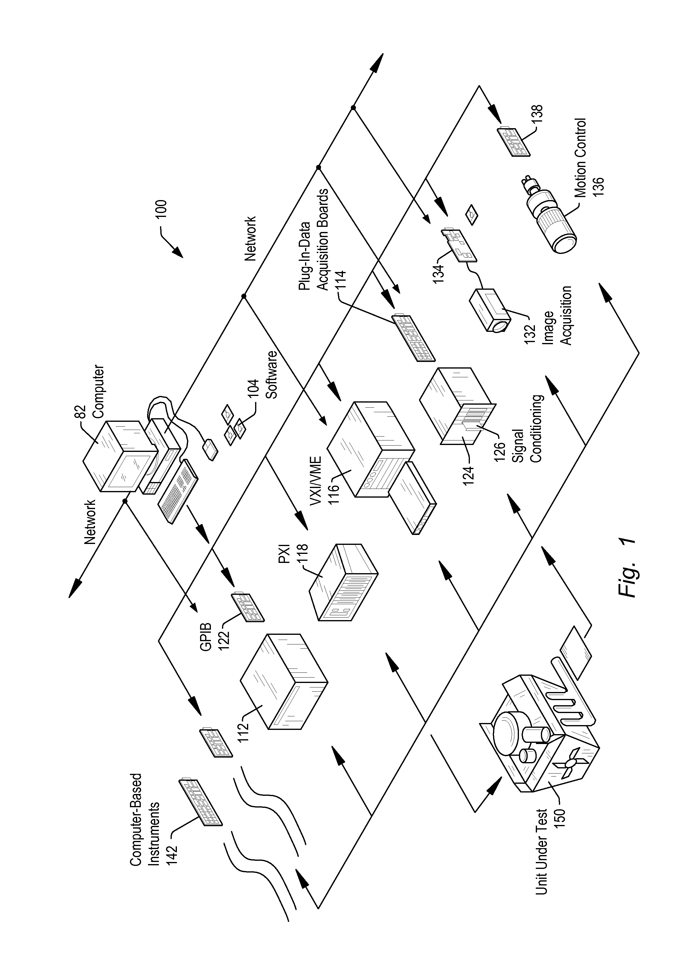
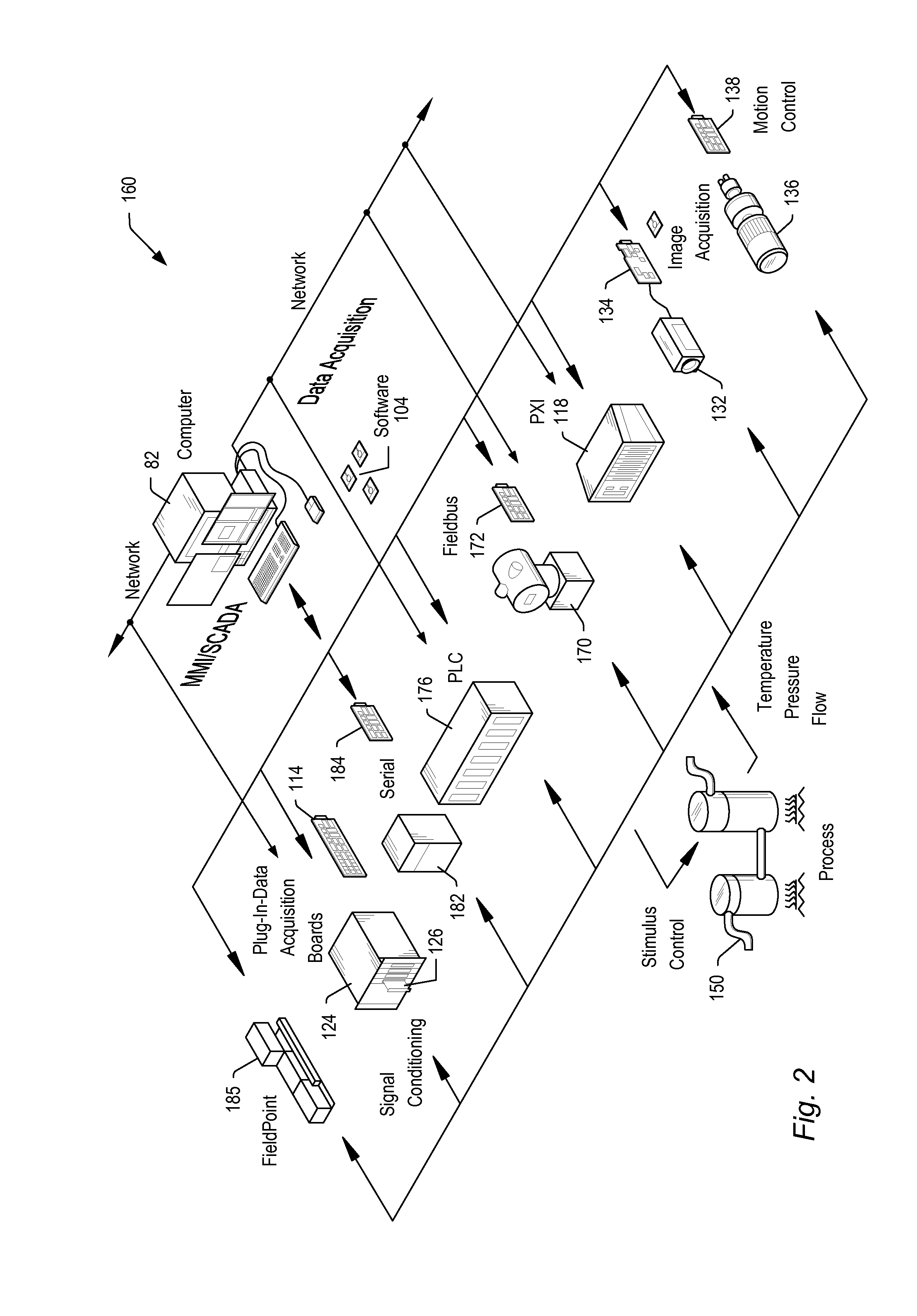
[0035]Embodiments of the present invention may be used in systems configured to perform test and / or measurement functions, to control and / or model instrumentation or industrial automation hardware, or to model and simulate functions, e.g., modeling or simulating a device or product being developed or tested, etc. More specifically, it may be used in various instances where input protection for instrumentation equipment is required, without degrading the performance of the protected instrumentation equipment. However, it is noted that the present invention may equally be used for a variety of applications, and is not limited to the applications enumerated above. In other words, applications discussed in the present description are exemplary only, and the present invention may be used in any of various types of systems. Thus, the system and method of the present invention may be used in any number of different applications. It is noted that the various terms or designations for circui...


PUM


Abstract

An improved measurement circuit includes a current transformer and an active feedback circuit operated as a negative resistance that matches the value of the winding resistance of the current transformer. An amplifier in the feedback circuit provides power to drive a secondary current through a sense resistor and the transformer winding resistance, reducing the most significant error source in a current transformer circuit by presenting a negative impedance to the current transformer. Combined with the positive resistance of the transformer's winding, the negative impedance results in a net burden of zero on the current transformer, which eliminates the need for the transformer having to provide power to drive the secondary current. This facilitates the use of smaller transformers while achieving reduced measurement errors. Thus, a single, compact measurement device may be used in a wide range of applications with high measurement performance.

Description

FIELD OF THE INVENTION[0001]The present invention relates to the field of instrumentation, and more particularly to compensating for inaccuracies in current transformers used in performing measurements for power monitoring.DESCRIPTION OF THE RELATED ART[0002]In many industrial applications (and others), instruments collect data or information from an environment or unit under test (UUT), and may also analyze and process acquired data. Some instruments provide test stimuli to a UUT. Examples of instruments include oscilloscopes, digital multimeters, pressure sensors, arbitrary waveform generators, digital waveform generators, etc. The information that may be collected by respective instruments includes information describing voltage, resistance, distance, velocity, pressure, oscillation frequency, humidity, and / or temperature, among others. Computer-based instrumentation systems typically include transducers for capturing a physical phenomenon and generating a representative electric...

Claims


Application Information

Patent Timeline
Patent Type & Authority Applications(United States)
IPC IPC(8): G01R19/32H03H11/52G01R19/00
CPCG01R19/32H03H11/52G01R19/0092
Inventor FOOTE, GARRITT W.
Owner NATIONAL INSTRUMENTS
Why Eureka
Try Eureka