Reconfigurable Output Matching Network for Multiple Power Mode Power Amplifiers

a power amplifier and output matching technology, applied in the direction of automatic tone/bandwidth control, gated amplifiers, gain control, etc., can solve the problems of reducing the efficiency of pa with a decrease of the input signal power level, conventional pa normally operates inefficiently at a middle power mode, and very inefficient at a low power mode. , to achieve the effect of efficient amplification of power amplifiers, reducing the complexity of amplifier circuits, and reducing the introduction of extra losses

Active Publication Date: 2014-09-25
MURATA MFG CO LTD
View PDF4 Cites 9 Cited by
  • Summary
  • Abstract
  • Description
  • Claims
  • Application Information

AI Technical Summary

Benefits of technology

[0017]The matching components can be in the form of lumped inductors and capacitors, but not at all limited to them. Any components having certain inductance and capacitance can be used as the matching elements. For example, the parasitic effects of bonding wires can function as inductors. The air gap between transmission lines or the open ended transmission lines effect can be treated as capacitance. Also, the components can be manufactured using different processes, such like surface mounted technology (SMT), MMIC (monolithic microwave integrated circuit), and radio frequency integrated circuit RFIC) using various semiconductor processes.
[0018]It is realized that it is advantageous to design the reconfigurable impedance matching network to minimize extra losses introduced by switching elements. The reduced number of the switching elements reduces the complexity of the amplifier circuit as well as the controlling. The efficient amplification of a power amplifier can be obtained by using the invented reconfigurable matching network at different output power levels.

Problems solved by technology

This is a problem for mobile devices that are battery operated, such as cellular telephones, and other wireless devices.
The performance of PA is also affected by manufacturing and packaging procedures.
In general, the efficiency of the PA degrades with a decrease of the input signal power level.
Consequently, the conventional PA normally operates inefficiently at a middle power mode, and very inefficiently at a low power mode, in comparison with high power mode operation.
This inefficiency is more severe in the smart phones for third and fourth generation (3G 4G) mobile communication that use a varying amplitude modulated RF signal.
This implies that the RF PA operates inefficiently most of the time under these scenarios.
Although the Doherty amplifier is capable of offering relative high efficiency at peak power level and at average power level, it is not very suitable for mobile devices because of its large size, and inherent limited bandwidth.
However, the main limitation and challenges of applying ET to mobile devices come from extra circuit modules (power modulator), and challenges of envelope signal alignment, and cost.
However, disadvantages of the stage-bypass technique include the complexity due to the number of amplifiers.
The design becomes more complicated for multi-band PA modules, where the PAs operate work at different frequency hands.
However, the extra complexities, power loss, reliabilities of the switchable and / or tunable elements are a disadvantage of the load modulation approach, when the matching network is not properly designed.

Method used


Image

  • Reconfigurable Output Matching Network for Multiple Power Mode Power Amplifiers
  • Reconfigurable Output Matching Network for Multiple Power Mode Power Amplifiers
  • Reconfigurable Output Matching Network for Multiple Power Mode Power Amplifiers

Examples


Embodiment Construction

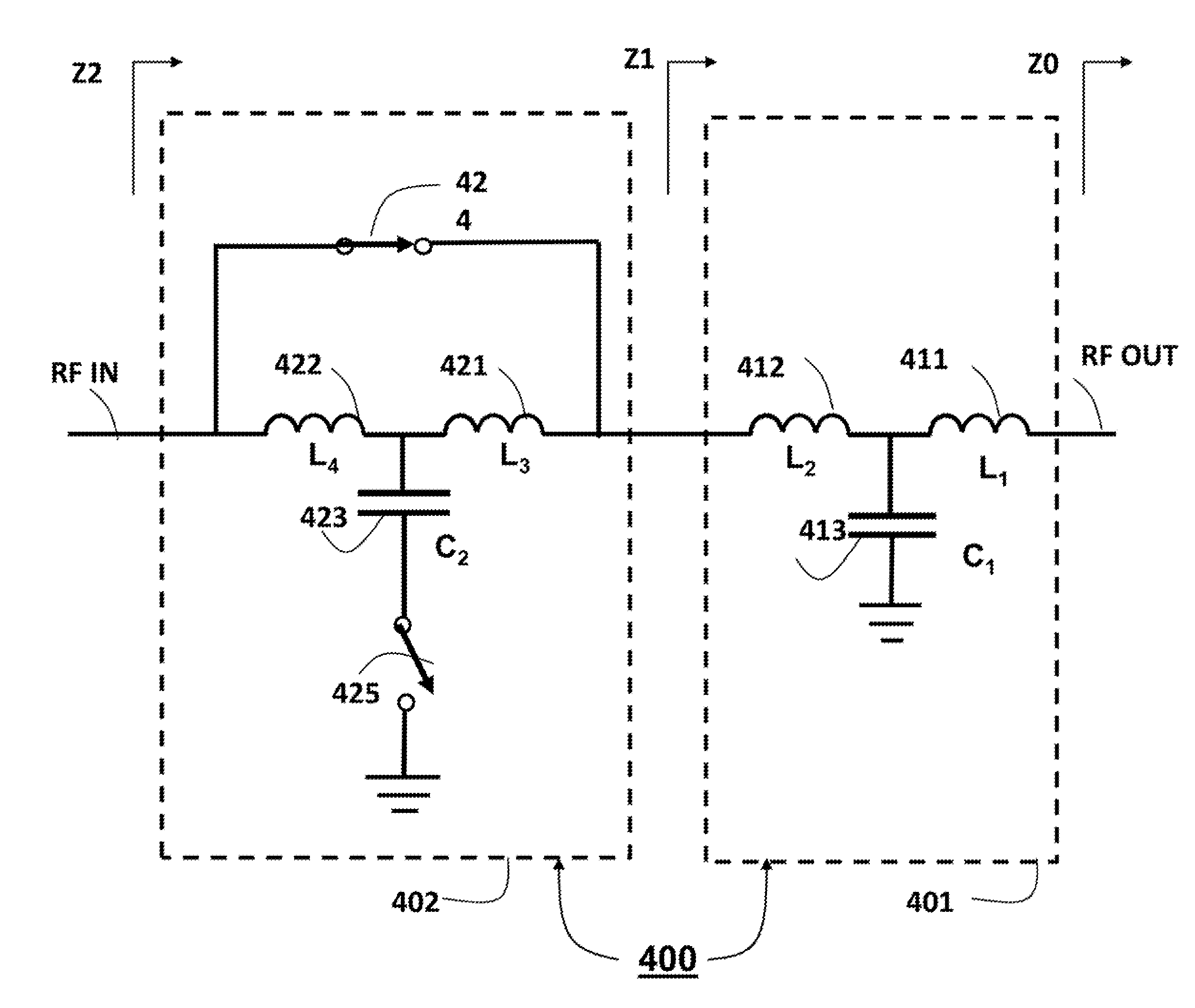
[0027]The embodiments of the invention provide an N-stage reconfigurable impedance matching network for N-different power modes.

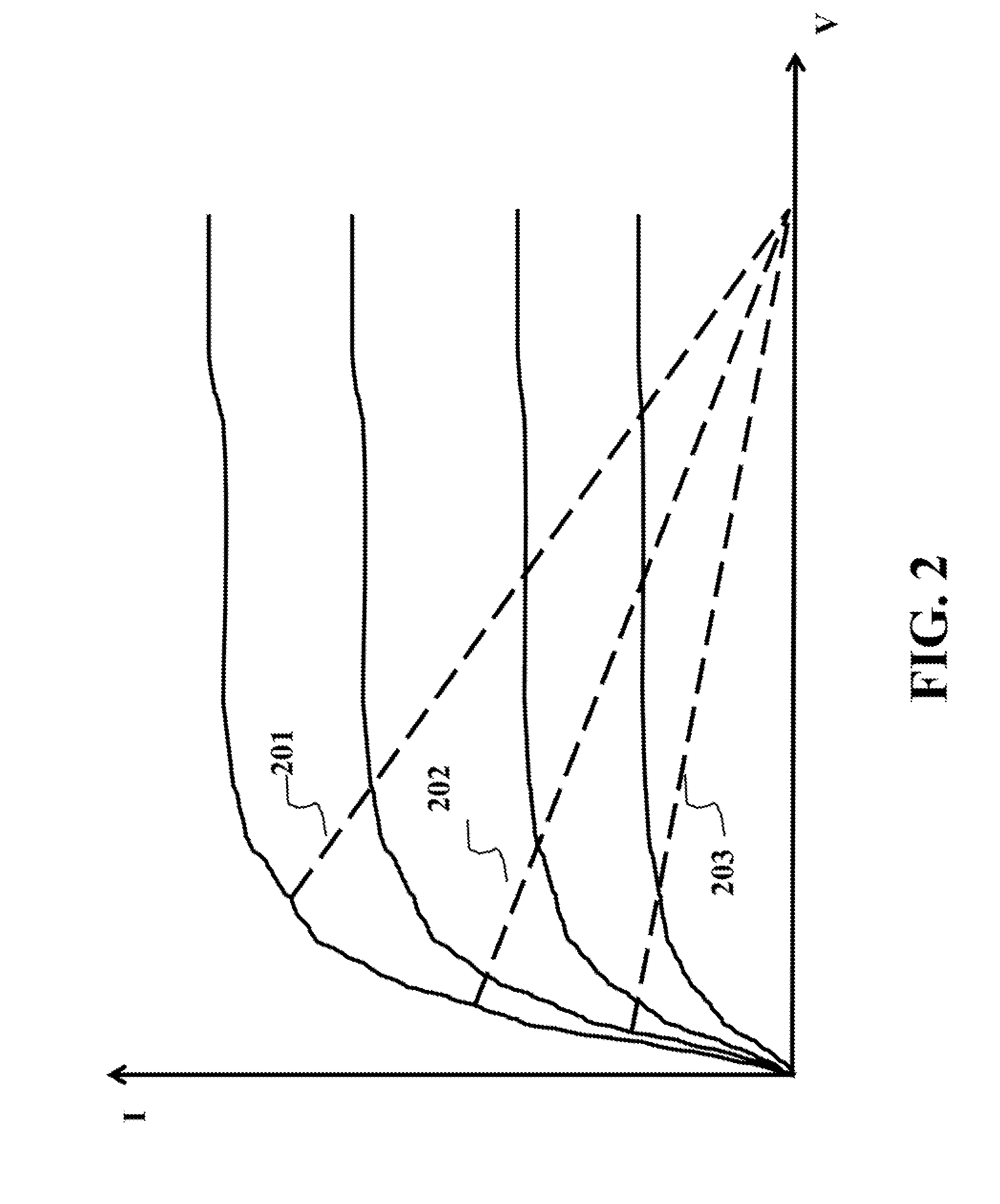
[0028]FIG. 2 shows loadlines as a function of current and voltage for three different power modes used by embodiments of the invention. For middle and low power mode, the load impedance is adjusted to higher impedances. The impedance is reverse to the slope of the dashed lines. The impedance is just the resistance indicated by line 201, 202, and 203 for simplification, corresponding to the optimal load resistance required by a transistor at low, middle and high power modes, respectively.

[0029]Thus, a power amplifier (PA) operates at nearly saturated regions for different power modes with high efficiency. The advantage of the load modulation compared with the stage-bypass is a relative simpler circuitry with fewer active devices.

[0030]The loadline, simplified to pure resistance, slope k=1 / Ropt (optimal resistance) is the required impedance value for terminat...


PUM


Abstract

An impedance matching network for a radio frequency (RF) amplifier includes multiple stages connected to each other in a first to last order. A first stage produces an RE output signal, and a last stage receives an RF input signal. Each stage includes a first inductor connected to produce an output signal, a second inductor connected to receive an input signal from a next stage, a capacitor connected between the first and second inductors and a ground. In addition, each stage other than the first stage further includes a first switch to by-pass the first and second inductors, a second switch connected between the first and second inductors and the ground, and a controller for controlling, the first and second switches to select a particular power level of a set of power levels.

Description

FIELD OF THE INVENTION[0001]The present invention relates generally to an impedance matching network for power amplifiers, and more particularly to impedance matching networks for multiple power mode radio frequency power amplifiers.BACKGROUND OF THE INVENTION[0002]In a transmitter, a radio frequency (RF) power amplifier (PA) consumes the most energy. This is a problem for mobile devices that are battery operated, such as cellular telephones, and other wireless devices. The RF PA affects the performance in terms of efficiency, linearity, and output power. The efficiency of the PA for converting the battery power to RF power of the signal determines to a great extent the length of time the device can be used before recharging, if at all possible.[0003]The efficiency of the PA is dependent on factors including, but not limited to, semiconductor technologies, amplifier architecture, mode of operation, and an impedance matching network. The performance of PA is also affected by manufact...

Claims


Application Information

Patent Timeline
Patent Type & Authority Applications(United States)
IPC IPC(8): H03G3/00
CPCH03G3/008H03F1/0277H03F1/565H03F3/189H03F3/245H03F3/72H03F2200/387H03F2200/391H03F2200/417H03F2200/421H03F2203/7215H03F2203/7221H03F2203/7236H03F3/191
Inventor MA, RUIGOSWAMI, SUSHMITTEO, KOON HOODUAN, CHUNJIE
Owner MURATA MFG CO LTD
Why Eureka
Try Eureka