
Broadband butler matrix device

a butler matrix and broadband technology, applied in waveguide devices, individual energised antenna arrays, multiple-port networks, etc., can solve the problem of phase differences between output terminals of such devices that are not uniform within an operating frequency band

Inactive Publication Date: 2014-09-25
ELECTRONICS & TELECOMM RES INST
View PDF2 Cites 17 Cited by
  • Summary
  • Abstract
  • Description
  • Claims
  • Application Information

AI Technical Summary

Benefits of technology

The present invention provides a device that can maintain specific phase differences of output terminals of a butler matrix, which results in a more equal distribution of signals across the network.

Problems solved by technology

However, the conventional butler matrix device has a disadvantage in that phase differences between output terminals thereof are not uniform within an operating frequency band.

Method used


Image

  • Broadband butler matrix device
  • Broadband butler matrix device
  • Broadband butler matrix device

Examples


Embodiment Construction

[0032]Hereinafter, exemplary embodiments of the present invention will be described below in more detail with reference to the accompanying drawings. The present invention may, however, be embodied in different forms, and should not be construed as being limited to the embodiments set forth herein. Rather, these embodiments are provided so that this disclosure will be thorough and complete, and will fully convey the scope of the present invention to those skilled in the art. Throughout the disclosure, like reference numerals refer to like parts throughout the various figures and embodiments of the present invention.

[0033]Furthermore, the terms described below have been defined by considering functions in embodiments of the present invention, and may be defined differently depending on a user or operator's intention or practice. Therefore, the definitions of such terms are based on the overall descriptions in the present specification.

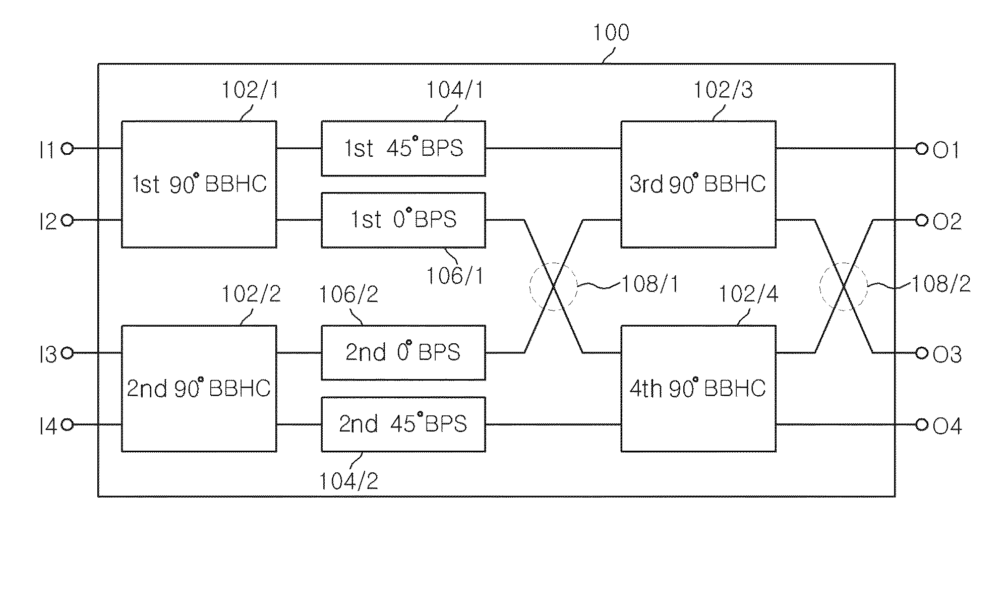
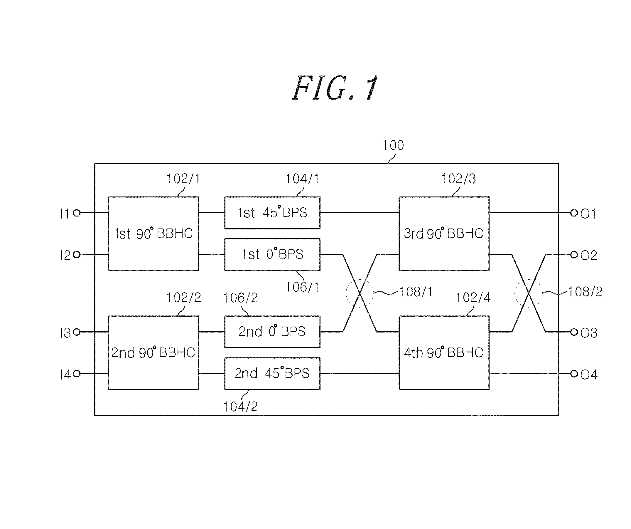
[0034]FIG. 1 is a configuration diagram of a broa...


PUM


Abstract

A broadband butler matrix device includes a 90° branch-line hybrid coupler having an input terminal provided at one side thereof and configured to receive an input signal through the input terminal, and distribute and output the received signal such that the distributed signals have a phase difference of 90°. Further, the broadband butler matrix device includes a 45° broadband phase shifter configured to change the phases of the signals outputted through the 90° branch-line hybrid coupler, using an open and short stub having an electrical length of 45°.

Description

CROSS-REFERENCE TO RELATED APPLICATION(S)[0001]The present invention claims priority of Korean Patent Application No. 10-2013-0029210, filed on Mar. 19, 2013, which is incorporated herein by reference.FIELD OF THE INVENTION[0002]The present invention relates to a broadband butler matrix device, and more particularly, to a broadband butler matrix device which is an ultra-high frequency part used for a multi-beam forming antenna.BACKGROUND OF THE INVENTION[0003]With the diversification of wireless communication services, demand for wireless frequency resources has been rapidly increased, and multiple input multiple output (MIMO) communication technology based on a broadband high-speed data service has been essentially required.[0004]According to the MIMO communication technology, multiple antennas are used to perform independent multiple channel transmissions, thereby increasing a channel capacity. Furthermore, multiple channels having directional characteristics and high isolation ch...

Claims


Application Information

Patent Timeline
Patent Type & Authority Applications(United States)
IPC IPC(8): H01P5/22
CPCH01P1/184H04B7/00H03H7/00H01Q3/00H01P5/227H01Q3/40H04B7/0615H01Q21/06H01Q3/34
Inventor KIM, JOUNG MYOUN
Owner ELECTRONICS & TELECOMM RES INST
Learn More