
Method and system for manufacturing a target for the emission of photon radiation, particularly x rays, or of particles, particularly protons or electrons, by laser firing

a laser firing and laser technology, applied in the field of protons and electrons, can solve the problems of long manufacturing process, besides very delicate substrate removal step, and vacuum reforming

Active Publication Date: 2014-09-25
COMMISSARIAT A LENERGIE ATOMIQUE ET AUX ENERGIES ALTERNATIVES
View PDF3 Cites 3 Cited by
  • Summary
  • Abstract
  • Description
  • Claims
  • Application Information

AI Technical Summary

Benefits of technology

The patent describes a method for creating a solid support for a target layer by filling openings in the support and removing the material used to fill the openings. The target layer is then formed on the solid support using a laser beam. The support is not removed and can be used to expose the target to the laser beam. The filling material can be easily removed by modifying pressure or temperature. The technical effects of this method include improved accuracy and stability of the target layer and easier removal of the filling material.

Problems solved by technology

Such a manufacturing is long and the substrate removal step is besides very delicate.
It is further necessary to introduce the target and its support into the enclosure, which assumes breaking the vacuum existing therein, and then reforming the vacuum, which also takes a long time.
In practice, the time of use of an X-ray emission system is very limited, and its down time is long.
Similar problems are posed for the generation of particles, for example, electrons and protons, by means of a laser firing on a thin target.

Method used


Image

  • Method and system for manufacturing a target for the emission of photon radiation, particularly x rays, or of particles, particularly protons or electrons, by laser firing
  • Method and system for manufacturing a target for the emission of photon radiation, particularly x rays, or of particles, particularly protons or electrons, by laser firing
  • Method and system for manufacturing a target for the emission of photon radiation, particularly x rays, or of particles, particularly protons or electrons, by laser firing

Examples


Embodiment Construction

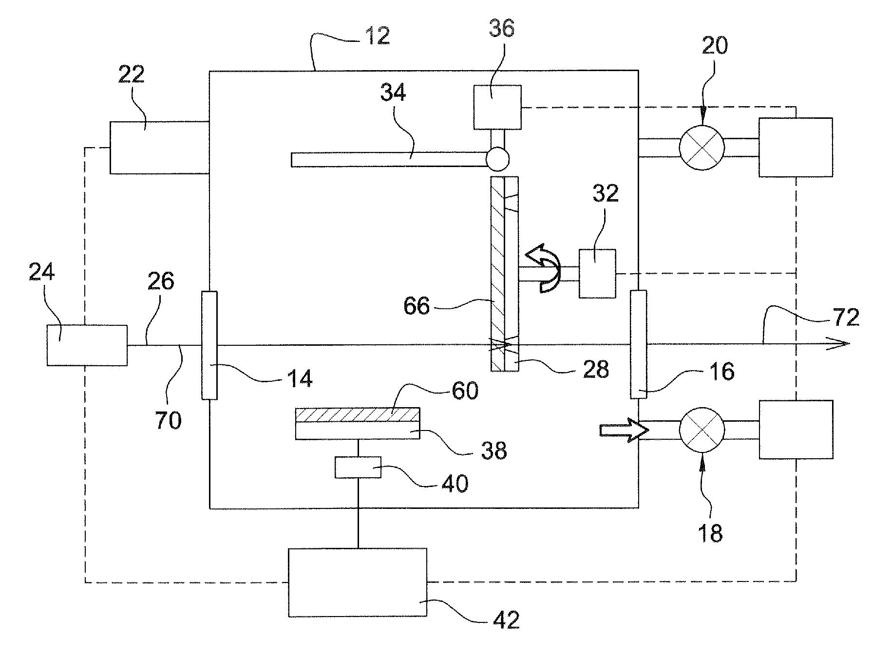
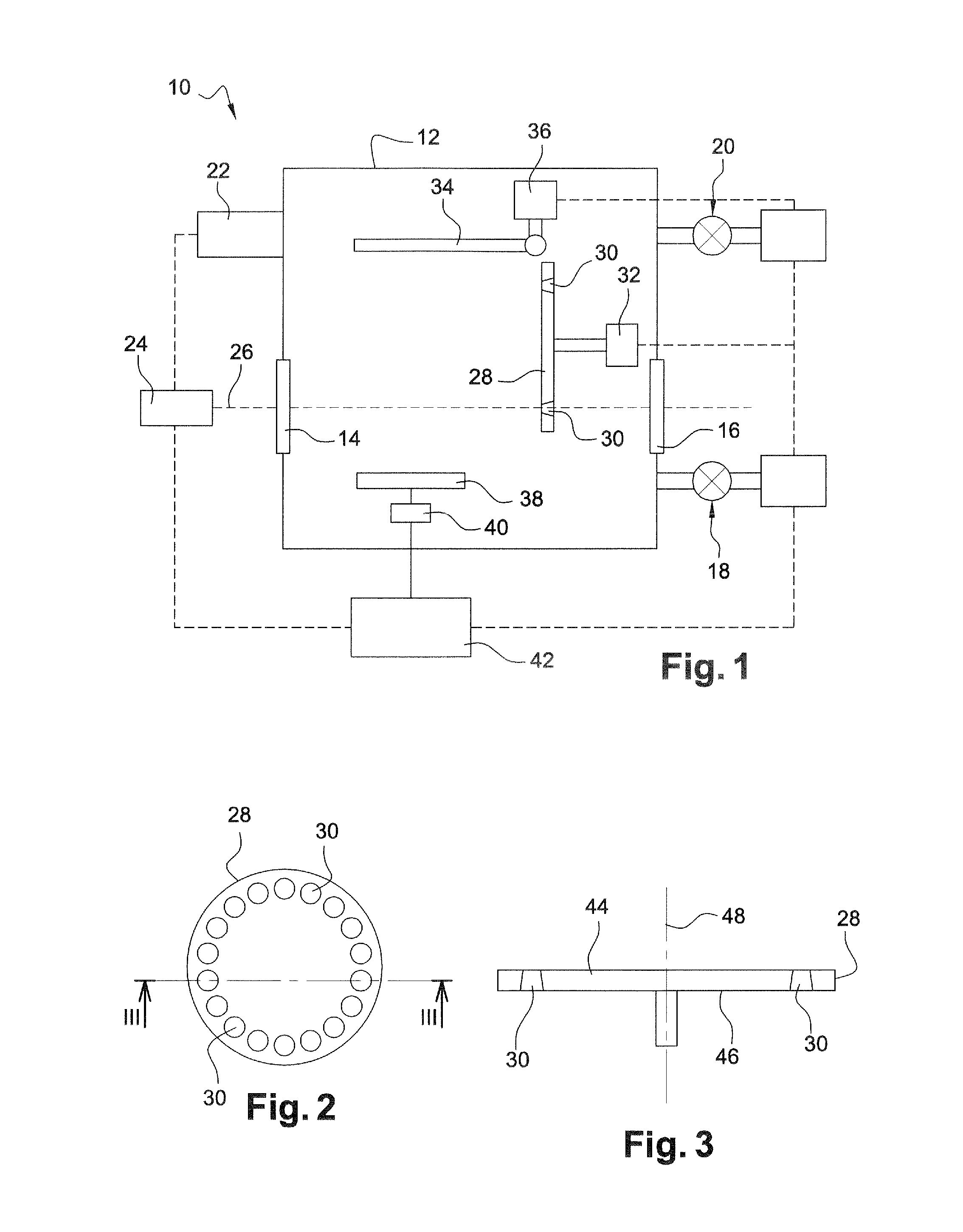
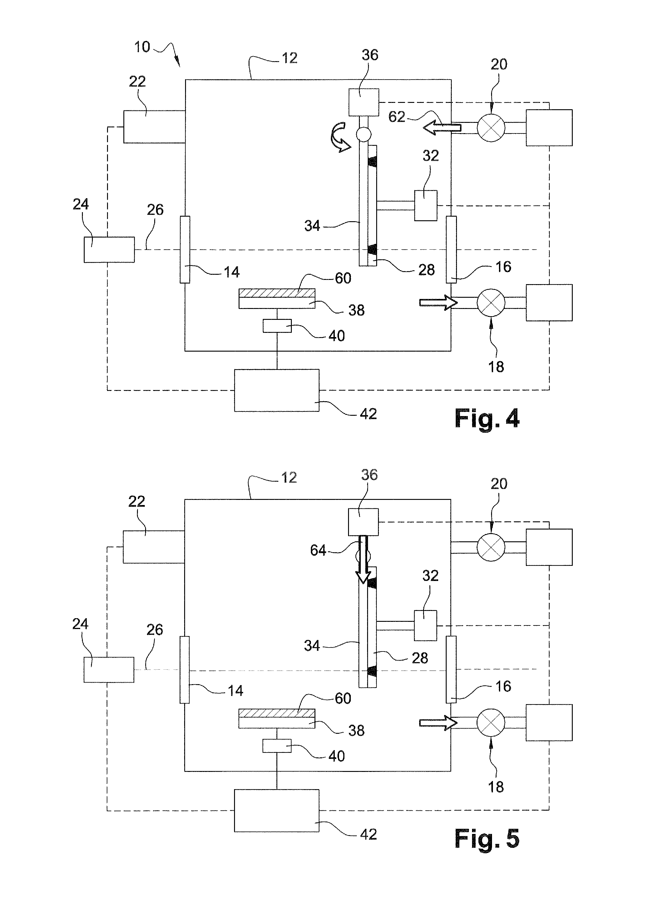
[0049]In relation with FIG. 1, a system 10 according to the invention enabling to form a metal target for the generation of X rays and to generate X rays from a single vacuum enclosure will now be described.

[0050]System 10 particularly comprises:[0051]a tight enclosure 12 comprising a first wall portion forming a first window 14 transparent to a laser beam, and a second wall portion forming a second window 16 transparent to X rays and arranged in front of first window 14. Tight enclosure 12 further comprises a heat shield enabling to limit heat inputs by radiation from the surrounding environment and from the elements internal to the enclosure having their temperature maintained high, for example, close to 300 K, for their operation.[0052]a pumping circuit 18 of enclosure 12, capable of creating therein a low pressure, particularly lower than 10−3 mbar, and more particularly a pressure lower than or equal to 10−4 mbar;[0053]an injection circuit 20 capable of injecting gas into enclo...


PUM

PropertyMeasurementUnit
Thicknessaaaaaaaaaa
Thicknessaaaaaaaaaa
Thicknessaaaaaaaaaa

Abstract

A method of manufacturing a target for the generation of radiation of photons, protons or electrons by means of a laser, including: forming a support including first and second surfaces connected by openings, and forming in an enclosure a layer of material on the first surface by protecting the first surface with a protection element, injecting into the enclosure a gas of filling material, adjusting the pressure in the enclosure and the temperature of the support to form plugs of material in the openings of the support, and maintaining the temperature of the support and the pressure in the enclosure at values to maintain the plugs, followed by withdrawing the protection clement from the first surface, and forming a layer of metallic material on the first surface of the support and on the plugs. The pressure and support temperature are then modified to remove the plugs.

Description

FIELD OF THE INVENTION[0001]The invention relates to the emission of X rays, or of particles, particularly protons and electrons, and more particularly to the manufacturing of targets used in such an emission.BACKGROUND[0002]A known principle of X-ray generation comprises focusing a laser beam on a solid metal target, preferably a metal having a high atomic number, for example, gold, copper, or any other dense metal. The interaction of the laser beam and of the metal thus generates a plasma and a mono-energetic X-ray emission, which are particularly used in mammography or angiography. The target is generally placed in a vacuum enclosure, where the laser / matter interaction takes place, and is mounted on a mobile support, for example, a rotating support, so that each laser firing impacts a portion of the target which has not been impacted by a previous tiring.[0003]When the metal target has a large thickness, particularly greater than 500 nanometer, the X rays are emitted in the half-...

Claims


Application Information

Patent Timeline
IPC IPC(8): C23C14/22C23C14/50C23C14/54C23C14/14C23C14/04
CPCC23C14/228C23C14/042C23C14/541C23C14/505C23C14/14H01J35/08H01J2235/085H05G2/001
Inventor PERIN, JEAN-PAUL
Owner COMMISSARIAT A LENERGIE ATOMIQUE ET AUX ENERGIES ALTERNATIVES
Learn More