
Brake control system and method for vehicle

Active Publication Date: 2014-10-02
HYUNDAI MOTOR CO LTD
View PDF5 Cites 7 Cited by
  • Summary
  • Abstract
  • Description
  • Claims
  • Application Information

AI Technical Summary

Benefits of technology

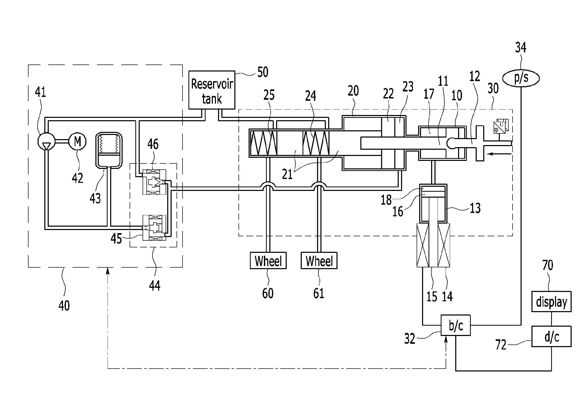
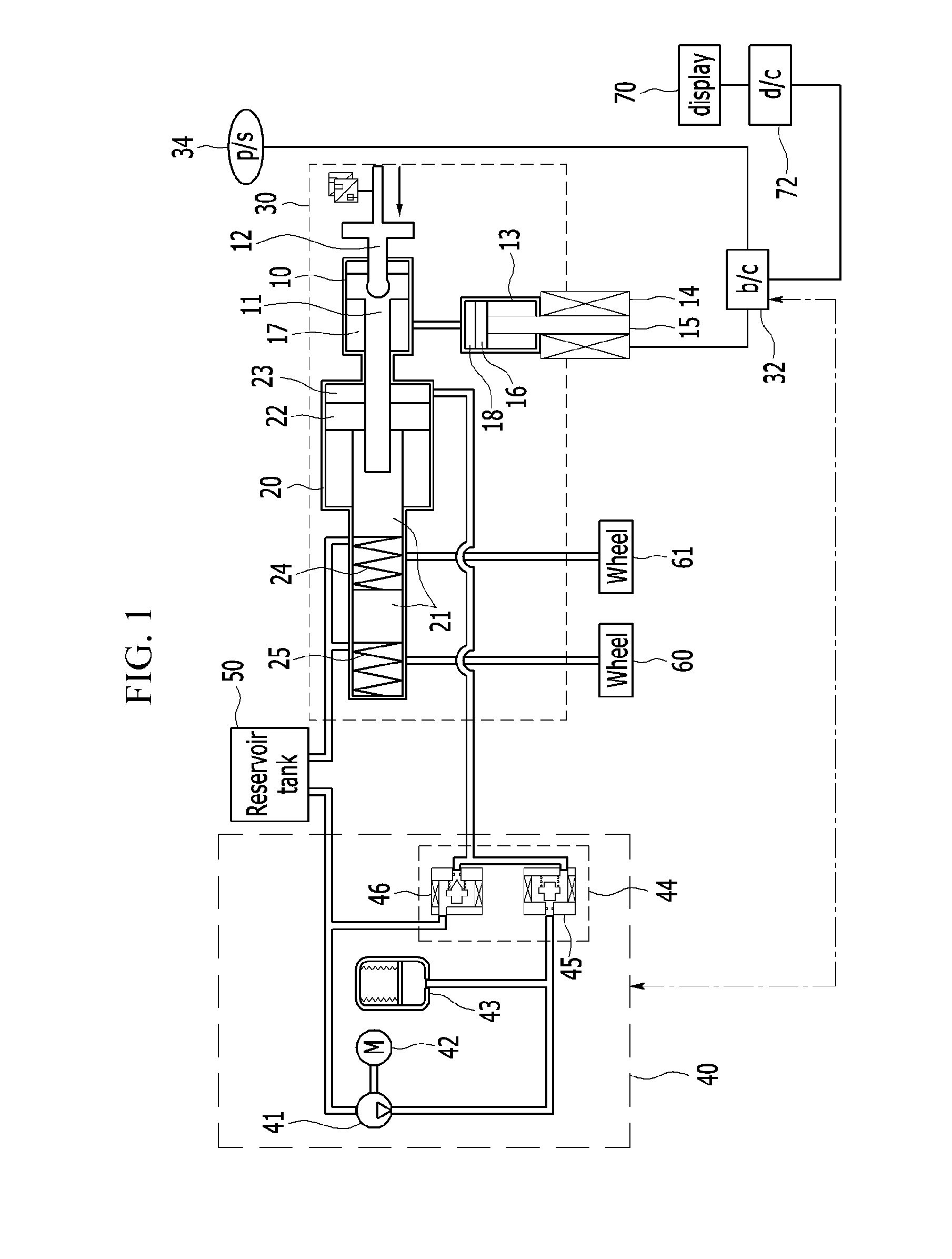
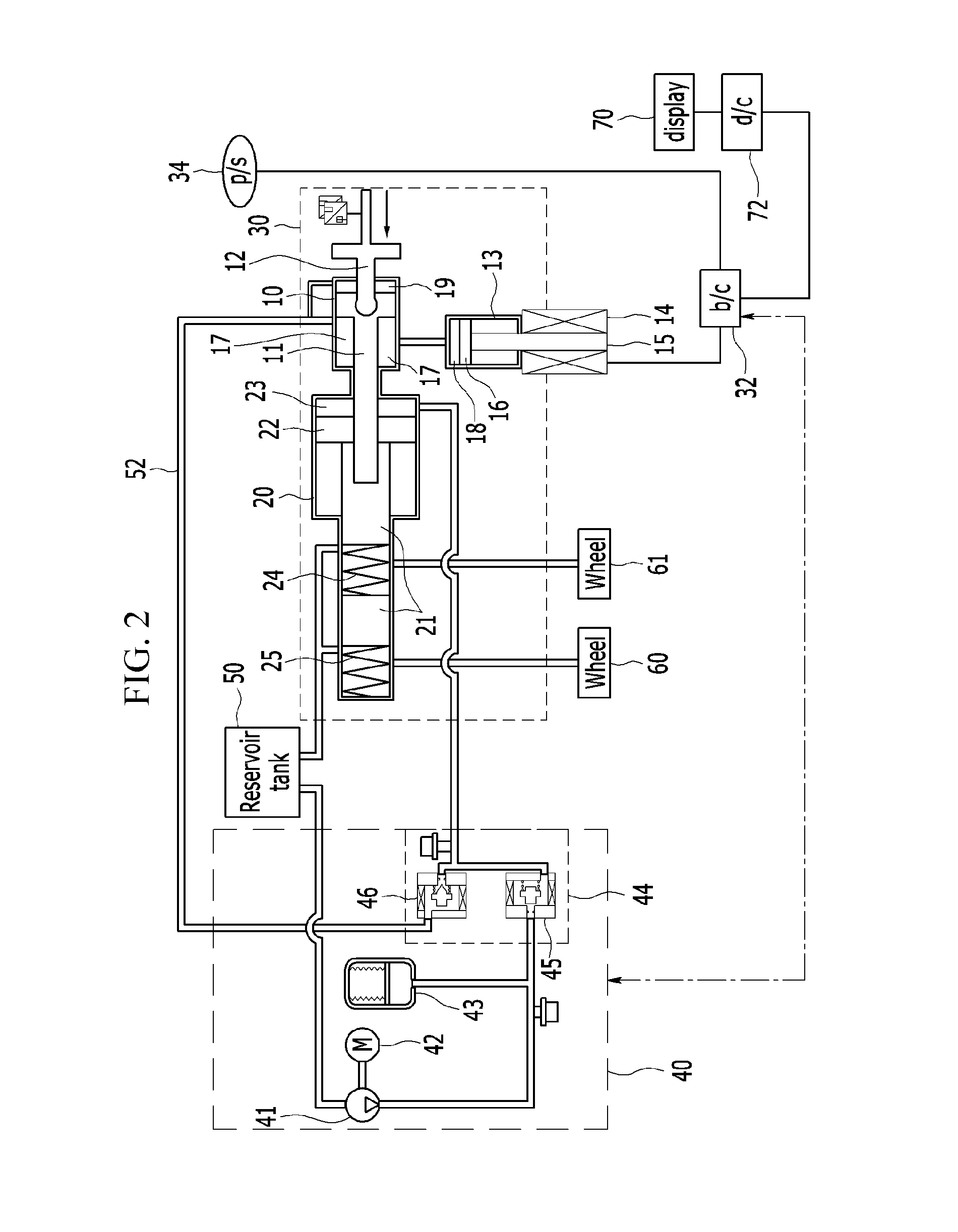
The present invention is a brake control system for vehicles that allows the driver to change the reaction force of the pedals based on their intention, and determine the effort required to press the pedals. This system ensures reliability and efficient braking performance.

Problems solved by technology

However, pedal effort may not be easily changed using a pedal simulator of the related art.
In addition, even though a change of pedal effort is implemented by the pedal simulator of the related art, a level thereof may be limited.

Method used


Image

  • Brake control system and method for vehicle
  • Brake control system and method for vehicle
  • Brake control system and method for vehicle

Examples


Embodiment Construction

[0024]It is understood that the term “vehicle” or “vehicular” or other similar term as used herein is inclusive of motor vehicles in general such as passenger automobiles including sports utility vehicles (SUV), buses, trucks, various commercial vehicles, watercraft including a variety of boats and ships, aircraft, and the like, and includes hybrid vehicles, electric vehicles, combustion, plug-in hybrid electric vehicles, hydrogen-powered vehicles and other alternative fuel vehicles (e.g. fuels derived from resources other than petroleum).

[0025]Although exemplary embodiment is described as using a plurality of units to perform the exemplary process, it is understood that the exemplary processes may also be performed by one or plurality of modules. Additionally, it is understood that the term controller / control unit refers to a hardware device that includes a memory and a processor. The memory is configured to store the modules and the processor is specifically configured to execute ...


PUM


Abstract

A brake control system and method that include a master cylinder that transmits braking hydraulic pressure to a wheel and a hydraulic power unit that supplies hydraulic pressure to the master cylinder to produce the braking hydraulic pressure transmitted to the wheel. A push rod is operated according to a brake pedal operation and a push rod cylinder is formed for the push rod to perform reciprocal motion in the push rod cylinder. A reaction force producer supplies hydraulic pressure to the push rod cylinder to produce reaction force against the push rod operation. A solenoid within the reaction force producer is operated by electric power to produce the reaction force. A pedal stroke sensor detects a brake pedal stroke and a brake control unit connected to the hydraulic power unit, the reaction force producer, and the pedal stroke sensor, operates the hydraulic power unit and the reaction force producer.

Description

CROSS-REFERENCE TO RELATED APPLICATION[0001]This application claims priority to and the benefit of Korean Patent Application No. 10-2013-0035369 filed in the Korean Intellectual Property Office on Apr. 1, 2013, the entire contents of which are incorporated herein by reference.BACKGROUND[0002](a) Field of the Invention[0003]The present invention relates to a brake control system and method for a vehicle, and more particularly, to a brake control system for a vehicle, applied to a hybrid vehicle to change reaction force of a pedal.[0004](b) Description of the Related Art[0005]In general, a cooperative control for regenerative braking system of a hybrid vehicle includes a hydraulic power unit that generates a pedal engagement signal, and amplifies and controls fluid pressure to control braking force of an accelerator pedal and a brake pedal to compensate for a pedal manipulating feeling. However, pedal effort may not be easily changed using a pedal simulator of the related art. In addi...

Claims


Application Information

Patent Timeline
IPC IPC(8): B60T13/14B60T17/22B60T8/40B60T7/04
CPCB60T13/145B60T8/409B60T17/22B60T7/04B60T8/4077B60T8/4086B60T7/042B60T13/143B60T11/16B60T11/232B60T7/06
Inventor JEON, GAB BAE
Owner HYUNDAI MOTOR CO LTD
Learn More