V+hu 2 +l Power Converter Control with Capacitor Current Ramp Compensation

a power converter and capacitor technology, applied in the direction of power conversion systems, dc-dc conversion, instruments, etc., can solve the problems of large size, relatively short usable lifetime, and limit and achieve the effect of limiting the application for which the power converter may or may not be appropria

Active Publication Date: 2014-10-02
VIRGINIA TECH INTPROP INC
View PDF3 Cites 64 Cited by
  • Summary
  • Abstract
  • Description
  • Claims
  • Application Information

AI Technical Summary

Benefits of technology

[0006]It is therefore an object of the present invention to provide a power converter and method of use of a low ESR capacitor for inductor or load current sensing that does not cause instability at practical converter / regulator switching frequencies.

Problems solved by technology

However, types of capacitors that have sufficient ESR for current sensing such as so-called OSCON™ or POSCAP™ capacitors are of large size and relatively short usable lifetimes. For these reasons, so-called ceramic capacitors (which generally but not necessarily include a component of ceramic material) are generally preferred in commercial power management products for their characteristically small size and long lifetime although use of ceramic capacitors as the output capacitor of a V2 controlled converter causes instability (referred to as sub-harmonic instability) at practical switching frequencies within several MHz.
Additionally, even when the switching frequency is greater than several MHz, and the system is theoretically stable, jittering (because the ripple magnitude is small and decreases with increasing switching frequency compared with inevitable noise) is unacceptable.
Several approaches to stabilizing or compensating voltage feedback control, and V2 control, in particular, using ceramic capacitors have been proposed but each has presented additional problems that limit the application for which the power converter may or may not be appropriate.

Method used


Image

  • V+hu 2 +l Power Converter Control with Capacitor Current Ramp Compensation
  • V+hu 2 +l Power Converter Control with Capacitor Current Ramp Compensation
  • V+hu 2 +l Power Converter Control with Capacitor Current Ramp Compensation

Examples


Embodiment Construction

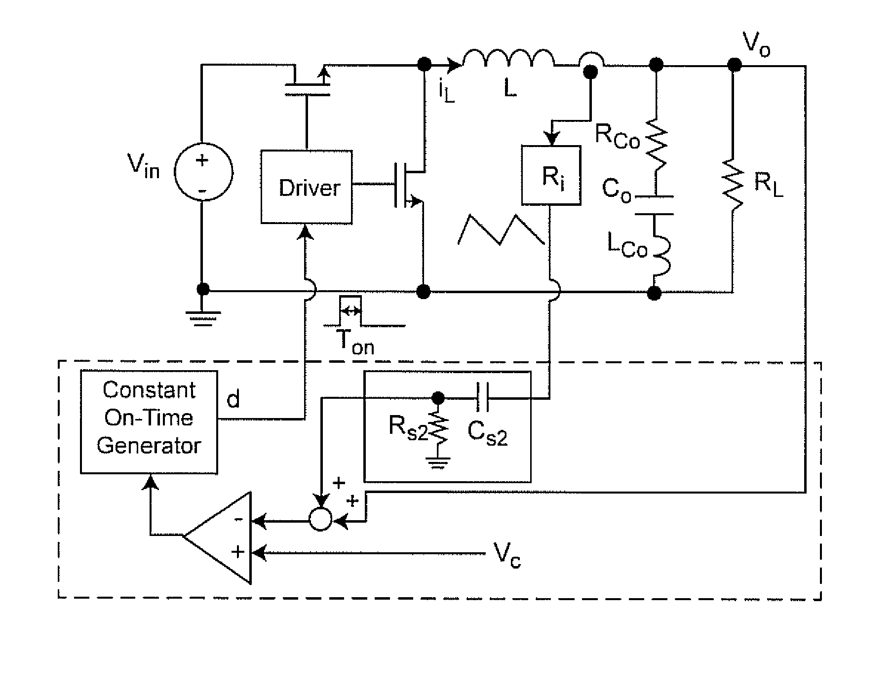
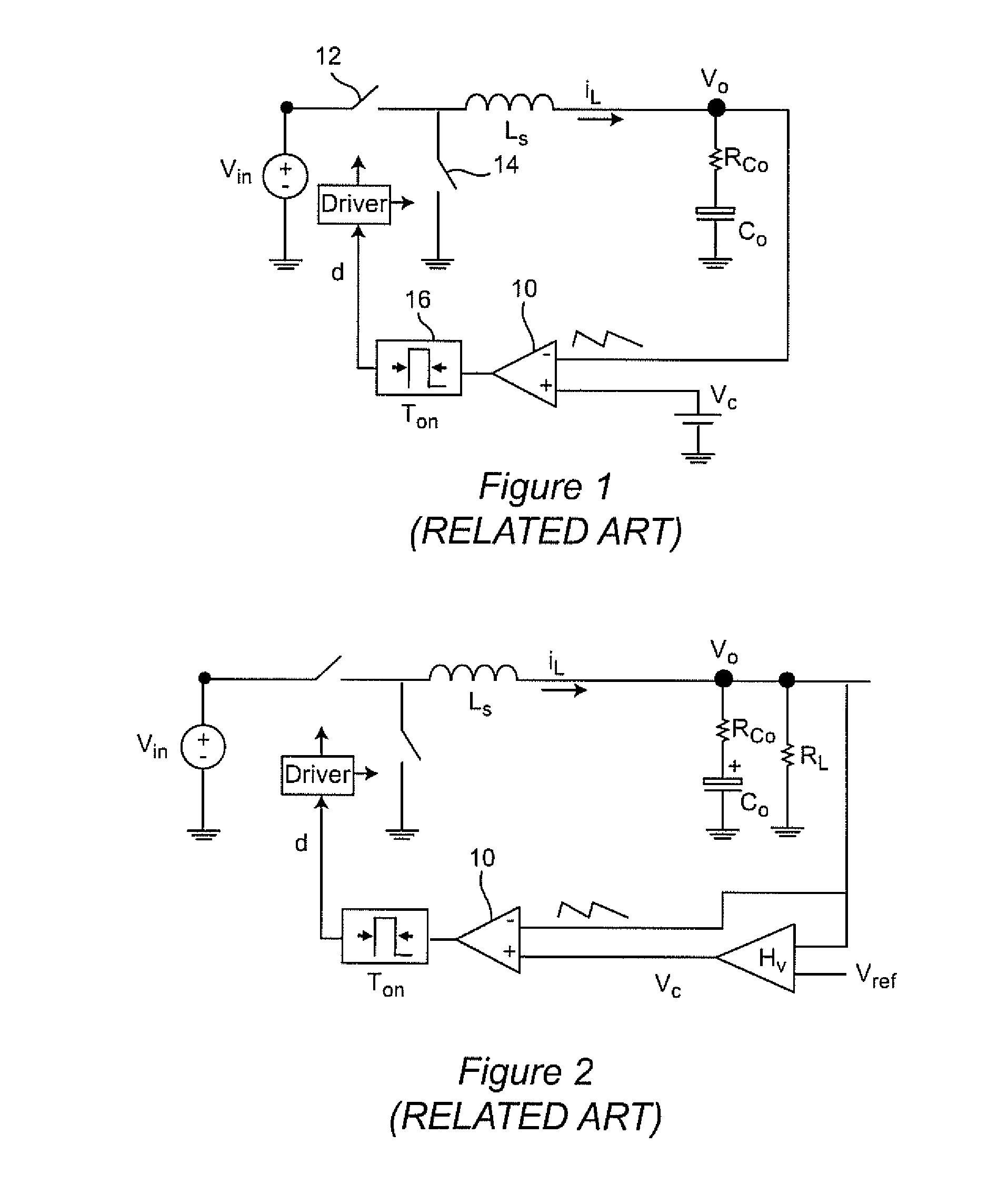
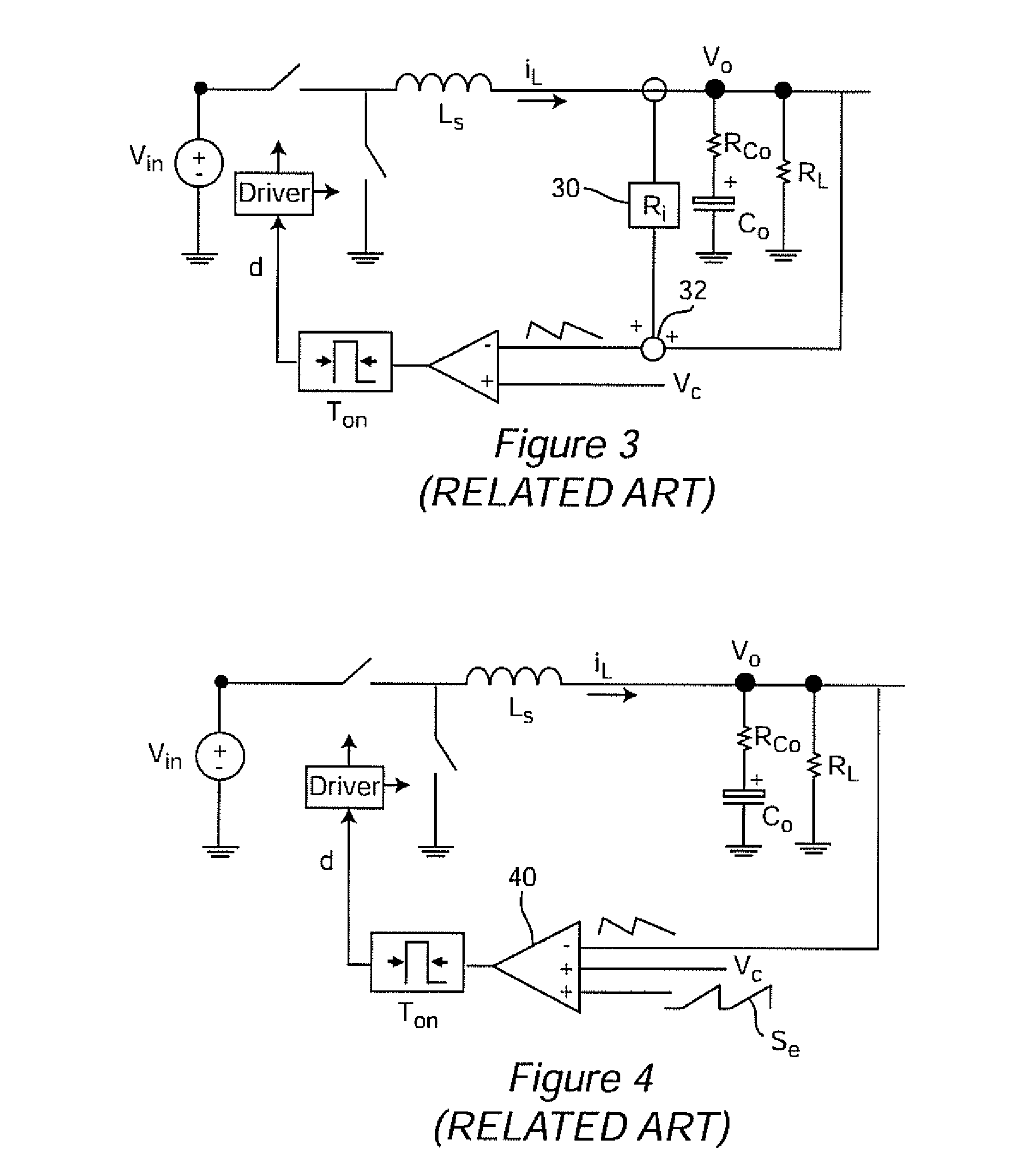
[0042]Referring now to the drawings, and more particularly to FIGS. 1 and 2, there is shown a buck converter having simple voltage feedback and voltage comparison control and a buck converter having V2 control, respectively. It is to be understood that these schematic diagrams are generalized and arranged to facilitate an understanding of the invention as will be discussed below through a comparison therewith. Therefore, no portion of either FIG. 1 or FIG. 2 is admitted to be prior art in regard to the present invention and these Figures have been labeled “Related Art”. It should also be understood that a buck converter is illustrated due to its simplicity and widespread choice for commercial products but that the invention as will be discussed in detail below is not limited to buck converters but can be applied to and practiced with a power converter or voltage regulator of any known or foreseeable topology.

[0043]It will be noted that the voltage in the feedback loop of FIG. 1 is a...


PUM


Abstract

Operation of a switching power converter having an output capacitor having a small equivalent series resistance (ESR) is stabilized and jitter reduced by sensing capacitor current with gain and combining the resulting signal with the output voltage signal to provide a feedback signal to control switching of the power converter. capacitor current can be sensed without interfering with operation of the filter capacitor by providing a branch circuit having a time constant matched to the output or filter capacitor but an arbitrarily high impedance so as to be effectively lossless. The gain provided in the capacitor current signal can be tuned to provide optimally short settling time after load transients; generally within one switching cycle. Matching of time constants and / or tuning of gain can be performed automatically.

Description

CROSS-REFERENCE TO RELATED APPLICATIONS[0001]This application claims benefit of priority of U.S. Provisional Application 61 / 806,457, filed Mar. 29, 2013, which is hereby incorporated by reference in its entirety.FIELD OF THE INVENTION[0002]The present invention generally relates to power converters and regulators and, more specifically, to voltage control of power converters and regulators using capacitor current sensing that is substantially lossless and capable of self-calibration and auto-tuning.BACKGROUND OF THE INVENTION[0003]Use of output voltage feedback arrangements has become popular for control of power converters and voltage regulators, particularly for point of load (POL) power supplies and voltage regulators for microprocessors where supplied voltage must be constrained within close tolerance even though load current may vary widely and rapidly. Some integrated circuits require not only regulation of voltage within close tolerances but also specify a reduction of voltag...

Claims


Application Information

Patent Timeline
Patent Type & Authority Applications(United States)
IPC IPC(8): H02M3/158
CPCH02M3/158H02M3/156H02M3/1566H02M3/157
Inventor YAN, YINGYILIU, PEI-HSINLEE, FRED C.
Owner VIRGINIA TECH INTPROP INC
Why Eureka
Try Eureka