
Electron beam melting furnace and method for operating same

Active Publication Date: 2014-10-02
TOHO TITANIUM CO LTD
View PDF1 Cites 3 Cited by
  • Summary
  • Abstract
  • Description
  • Claims
  • Application Information

AI Technical Summary

Benefits of technology

The invention allows for accurate heating of a molten metal pool without damaging the hearth and mold. This means that the entire hearth can be effectively used.

Problems solved by technology

In a case in which the vapor enters into the electron beam route, the electron beam and the metallic vapor interfere with each other, and as a result, there may be a case in which the direction of the electron beam is changed, and the electron beam cannot be emitted in the required direction that is set.
Furthermore, in addition to this situation inside of the electron beam melting furnace, there may be a case in which direction of the electron beam is changed to an undesirable direction by noise that entered from the outside.
Furthermore, it is well known that the electron beam and the deflection coil to bend the electron beam are easily influenced by an external magnetic field, and in that case, there may be a case in which the electron beam is bent to an undesirable direction, and thus, improvements for these problems has been required.
In the case in which the electron beam is spread in an unintended direction as described above, for example, the wall of the hearth in which molten metal is held may be heated, and in a case in which this heating is not considered for a long time, the hearth may be undesirably damaged.
However, there is no disclosure regarding correction of unintended displacement of location of the electron beam spot.
However, in this method, since erroneous operation can be detected after the erroneous emission of an electron beam, the mold cannot be prevented from being damaged, and the hearth may be undesirably significantly damaged.

Method used


Image

  • Electron beam melting furnace and method for operating same
  • Electron beam melting furnace and method for operating same
  • Electron beam melting furnace and method for operating same

Examples


example 1

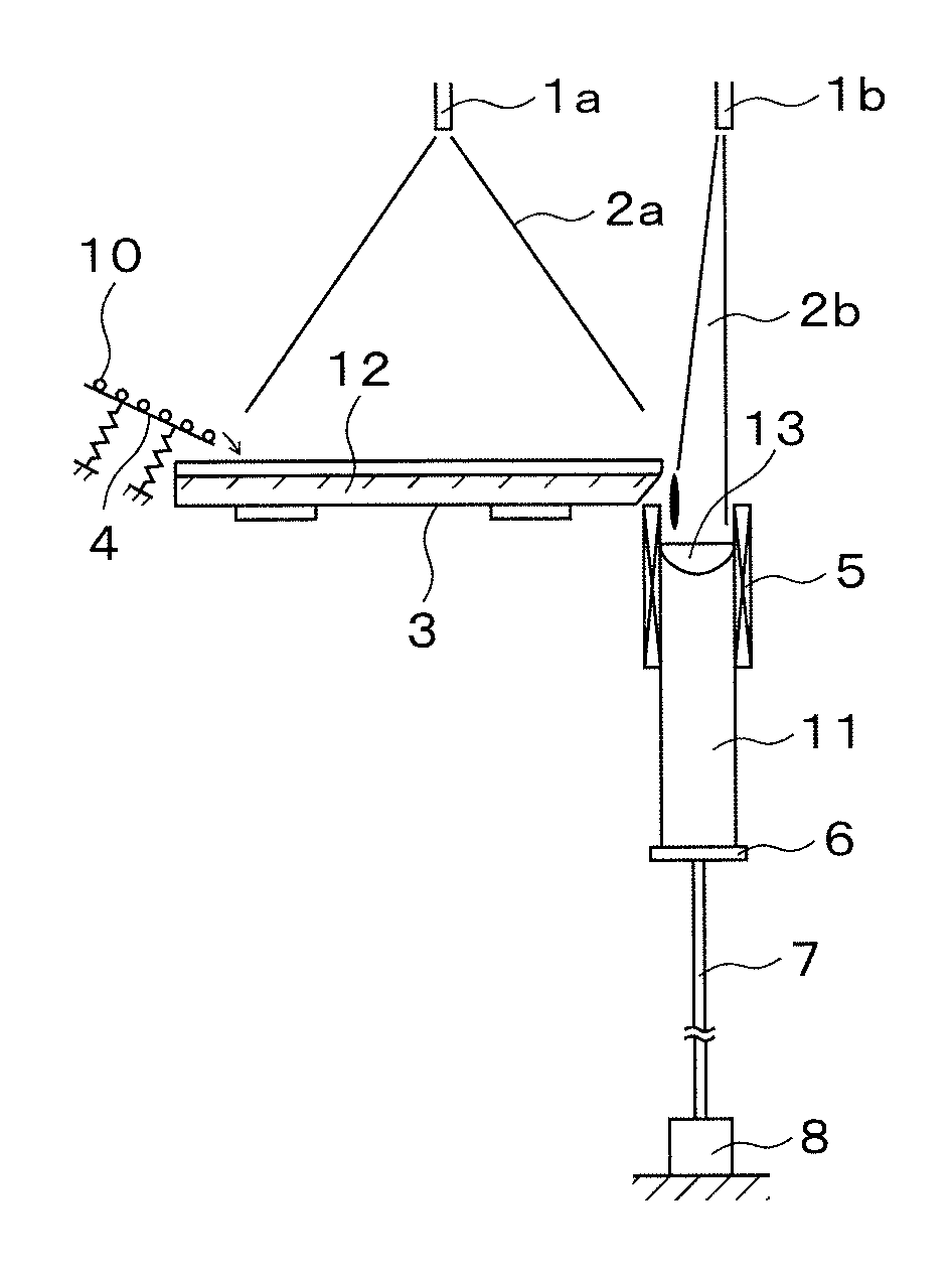
[0072]Using the above mentioned devices, titanium sponge was supplied to the hearth and melted to form molten metal, and this molten metal was poured into the mold to produce an ingot. After production of the ingot, as a result of observation of the hearth wall arranged in the electron beam melting furnace by the human eye, there was no damaged part found in the hearth.

example 2

[0074]An ingot was produced in a manner similar to that in the Example 1, except that alloy scrap was used as the raw material instead of sponge titanium. As a result of analyzing distribution of alloy component in the ingot produced, it was confirmed that variation was within 3% to 8% in relative error relative to the absolute value of the average value of the ingot, in each of the longitudinal direction and the radial direction.


PUM

PropertyMeasurementUnit
Lengthaaaaaaaaaa
Resolution enthalpyaaaaaaaaaa

Abstract

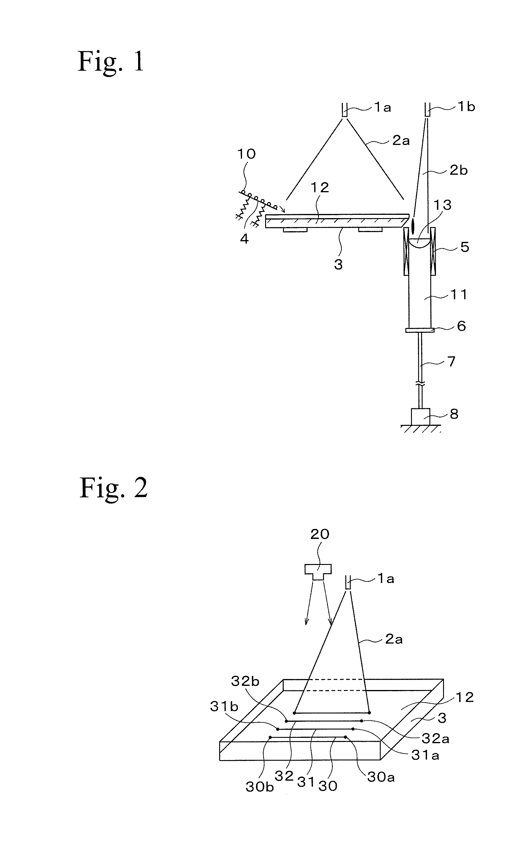
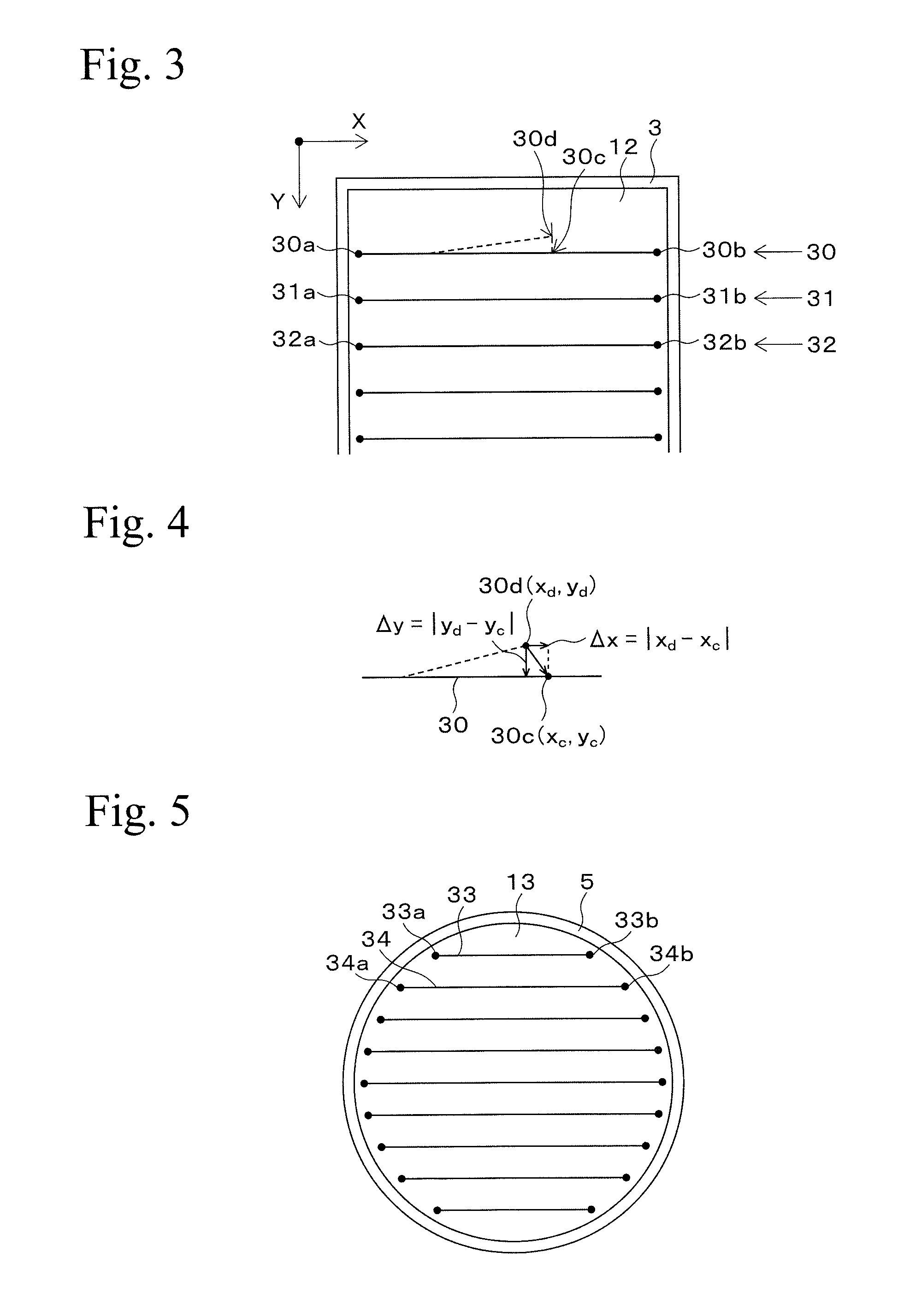
An electron beam is accurately emitted to a pre-set location on a molten metal pool formed in a hearth or a mold arranged in an electron beam melting furnace. The present invention provides a method for operating an electron beam melting furnace, the furnace includes: a hearth and a mold for holding molten metal, an electron gun for keeping the metal as a molten state, an electron beam controlling means for controlling direction of the electron beam, an image sensor for molten metal, and an operating means, and the method includes: a step of inputting coordinates in the electron beam controlling means at which an electron beam is to be emitted on molten metal, a step of emitting the electron beam on the molten metal, a step of detecting a high electron beam intensity spot generated by emitting an electron beam on the molten metal by the image sensor, a step of calculating coordinates of high electron beam intensity based on the detected signal by the operating means, a step of calculating differences between the coordinates of emission and the coordinates of high electron beam intensity spot, a step of inputting the difference in the electron beam controlling means, and a step of controlling the location of electron beam spot so that the difference be not more than pre-set value.

Description

TECHNICAL FIELD[0001]The present invention relates to a technique in which an electron beam is emitted on a molten metal pool formed in a mold or a hearth arranged in an electron beam melting furnace, and in particular, relates to a technique in which location of heating by the emission of electron beam is controlled.BACKGROUND ART[0002]It is well known that effects of purification of raw material are greater and much purer metal can be appropriately produced in an electron beam melting furnace since the degree of pressure reduction can be set lower compared to that in a vacuum arc melting furnace.[0003]Among electron beam melting furnaces, there are many cases in which a furnace for purification, called a hearth, is arranged therein. By melting raw material in the hearth, impurities contained in the raw material can be effectively removed, thereby enabling purification of the raw material.[0004]In an electron beam melting furnace, a target is heated and melted by emitting an electr...

Claims


Application Information

Patent Timeline
IPC IPC(8): H01J37/304
CPCH01J37/304B22D23/06C22B9/228F27D11/08B22D11/041B22D27/02H01J37/305C22C14/00F27D11/12F27D19/00F27D2019/0071H01J37/22H01J37/222H01J37/3045
Inventor ODA, TAKASHITANAKA, HISAMUNESHIRAKI, TAKESHI
Owner TOHO TITANIUM CO LTD
Learn More