
Power supply device and power supply method

Active Publication Date: 2014-10-09
TOYOTA JIDOSHA KK
View PDF3 Cites 11 Cited by
  • Summary
  • Abstract
  • Description
  • Claims
  • Application Information

AI Technical Summary

Benefits of technology

The invention aims to reduce the difference in the fee paid by a user when they receive power from a power supply device. This helps to make the user more understandable.

Problems solved by technology

However, when the uniform unit price is set for the power that is used for the charging, a charging cost may largely fluctuates in each time due to fluctuation of charging efficiency to the vehicle.
For example, an increase in loss due to aging degradation of the charging device and a power storage device can be considered as a cause.
However, in such a case, the charging efficiency may fluctuate due to a mismatch between a power transmission section and a power reception section, interposition of an object, sand, snow or the like between the power transmission section and the power reception section, or the like.

Method used


Image

  • Power supply device and power supply method
  • Power supply device and power supply method
  • Power supply device and power supply method

Examples


modification examples

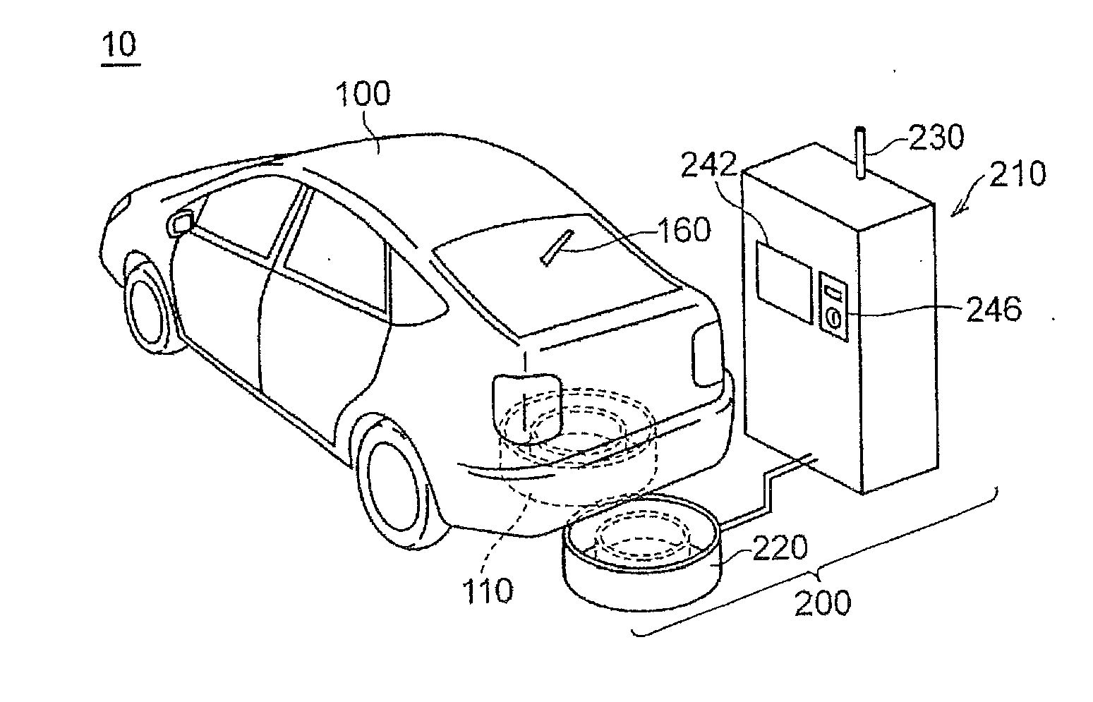
[0143]FIG. 13 is a diagram for illustrating a first modification example. Referring to FIG. 13, a power transmission-reception system 1010 of the first modification example includes a power transmission device 1200 and a vehicle 1100. The power transmission device 1200 performs power supply to the vehicle 1100 by a microwave.

[0144]The power transmission device 1200 includes a charging stand 1210 and a microwave power transmission section 1220. The charging stand 1210 has a similar configuration to the charging stand 210 illustrated in FIG. 6, and a description thereof will not be repeated.

[0145]The vehicle 1100 includes a microwave power reception section 1110 instead of the power reception section 110 in a configuration of the vehicle 100 illustrated in FIG. 6. A configuration of other sections of the vehicle 1100 is similar to that of the vehicle 100, and a description thereof will not be repeated.

[0146]The control illustrated in FIG. 10 to FIG. 12 can be applied to the power tran...


PUM


Abstract

A power supply device which performs power supply from an outside to a vehicle includes: a power source section for performing the power supply to the vehicle; and a control device that performs control of the power source section. The control device obtains information about power reception efficiency of the vehicle as an object of the power supply and determines a power reception efficiency range and a fee that correspond to the obtained information from a plurality of power reception efficiency ranges and plurality of fees that are set corresponding to the plurality of power reception efficiency ranges. The power supply device preferably further includes a power transmission section for receiving the power from the power source section and contactlessly performing power transmission to the vehicle.

Description

TECHNICAL FIELD[0001]The present invention relates to a power supply device and a power supply method and particularly to a power supply device and a power supply method in which power supply is performed to a vehicle from an outside.BACKGROUND ART[0002]Recently, electric vehicles and hybrid vehicles that travel with electric energy instead of fuel or in addition to fuel have been attracting attention in order to reduce carbon dioxide exhausted from automobiles to prevent global warming. Among hybrid vehicles, plug-in hybrid vehicles have been produced that are configured such that an installed battery can be charged with electric energy from an outside of the vehicle.[0003]Japanese Patent Application Publication No. 2007-62638 (JP 2007-62638 A) (Patent Document 1) discloses a hybrid vehicle in which the battery can be charged from the outside of the vehicle and that can be expected to reduce a power cost.PRIOR ART DOCUMENTS[0004]Patent Documents[0005]Patent Document 1: Japanese Pat...

Claims


Application Information

Patent Timeline
IPC IPC(8): B60L11/18G06Q50/06
CPCB60L11/1848B60L11/182G06Q50/06B60L53/122B60L53/126B60L53/665G06Q30/04Y02E40/70Y02T10/70Y02T10/7072Y02T90/12Y02T90/14Y04S10/50Y04S50/12
Inventor MIWA, KOJIKAWAI, TAKASHIICHIKAWA, SHINJI
Owner TOYOTA JIDOSHA KK
Learn More