
Control apparatus for internal combustion engine

a control apparatus and internal combustion engine technology, applied in the direction of electrical control, process and machine control, instruments, etc., can solve the problems of catalyst deterioration, increased negative pressure of intake, increased amount of blow-by gas introduced into the intake system, etc., to prevent catalyst ot or the like, increase the opening degree of the throttle valve, and restrain the negative pressure of intak

Active Publication Date: 2014-10-09
TOYOTA JIDOSHA KK
View PDF15 Cites 17 Cited by
  • Summary
  • Abstract
  • Description
  • Claims
  • Application Information

AI Technical Summary

Benefits of technology

The invention relates to a method for controlling the intake system of an engine to prevent excessive blow-by gas from entering the intake system and causing damage to the engine. The technical effects of the invention include reducing the negative pressure in the intake system, which reduces the amount of blow-by gas that enters during operation, and improving the driveability of the engine by creating a negative pressure during deceleration. Additionally, by increasing the opening degree of the throttle valve and controlling the timing of the intake valve closing, the amount of blow-by gas generated during fuel cutoff is minimized, preventing catalyst damage and ensuring good exhaust emission properties.

Problems solved by technology

Thus, during fuel cutoff, the intake negative pressure increases, and the amount of blow-by gas introduced into the intake system also tends to increase.
However, this blow-by gas flows out to an exhaust system without burning in the cylinder due to the execution of fuel cutoff, and reacts with oxygen on a catalyst.
Thus, in the conventional art, the internal combustion engine that is mounted with the PCV mechanism so as to cope with the use of alcohol fuel has a problem in that a large amount of blow-by gas reacts with oxygen on the catalyst during fuel cutoff, and that the catalyst is likely to deteriorate due to reaction heat thereof.

Method used


Image

  • Control apparatus for internal combustion engine
  • Control apparatus for internal combustion engine
  • Control apparatus for internal combustion engine

Examples


first embodiment

Concrete Processing for Realizing First Embodiment

[0050]Next, a concrete processing for realizing the first embodiment of the invention will be described with reference to FIG. 7. FIG. 7 is a flowchart showing the control performed by the ECU in the first embodiment of the invention. A routine shown in this drawing is repeatedly executed during operation of the engine. In the routine shown in

[0051]FIG. 7, first of all in step 100, an engine temperature (the engine coolant temperature ethw or the lubricating oil temperature etho) is acquired. In step 102, it is determined whether or not the engine temperature acquired in step 100 is equal to or higher than a predetermined temperature. That is, in step 102, it is determined whether or not the engine coolant temperature ethw is equal to or higher than the predetermined temperature T1 in the case where the engine coolant temperature ethw is used as the engine temperature, and it is determined whether or not the lubricating oil temperatu...


PUM


Abstract

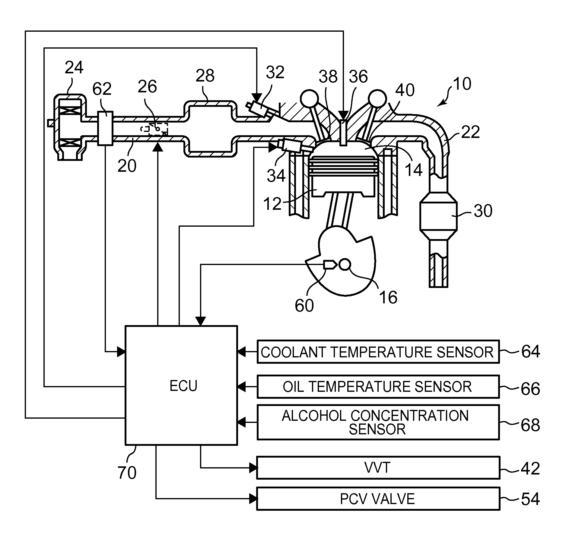
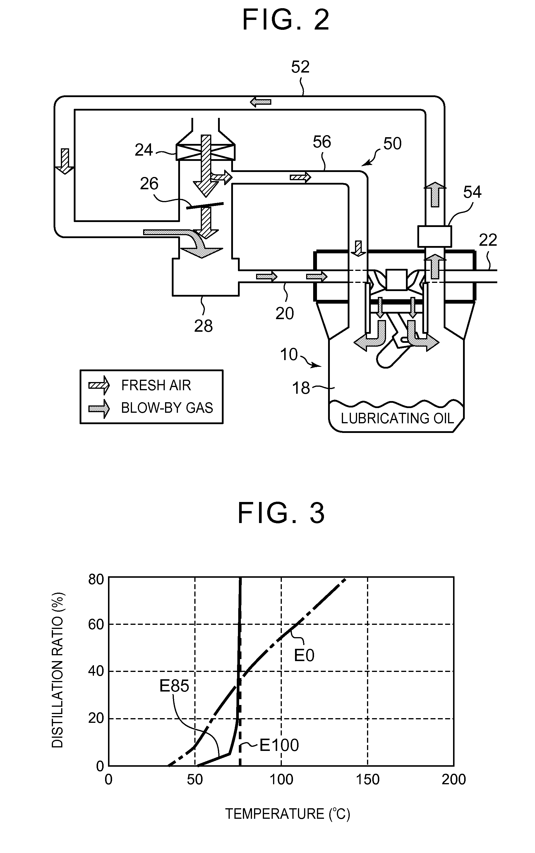
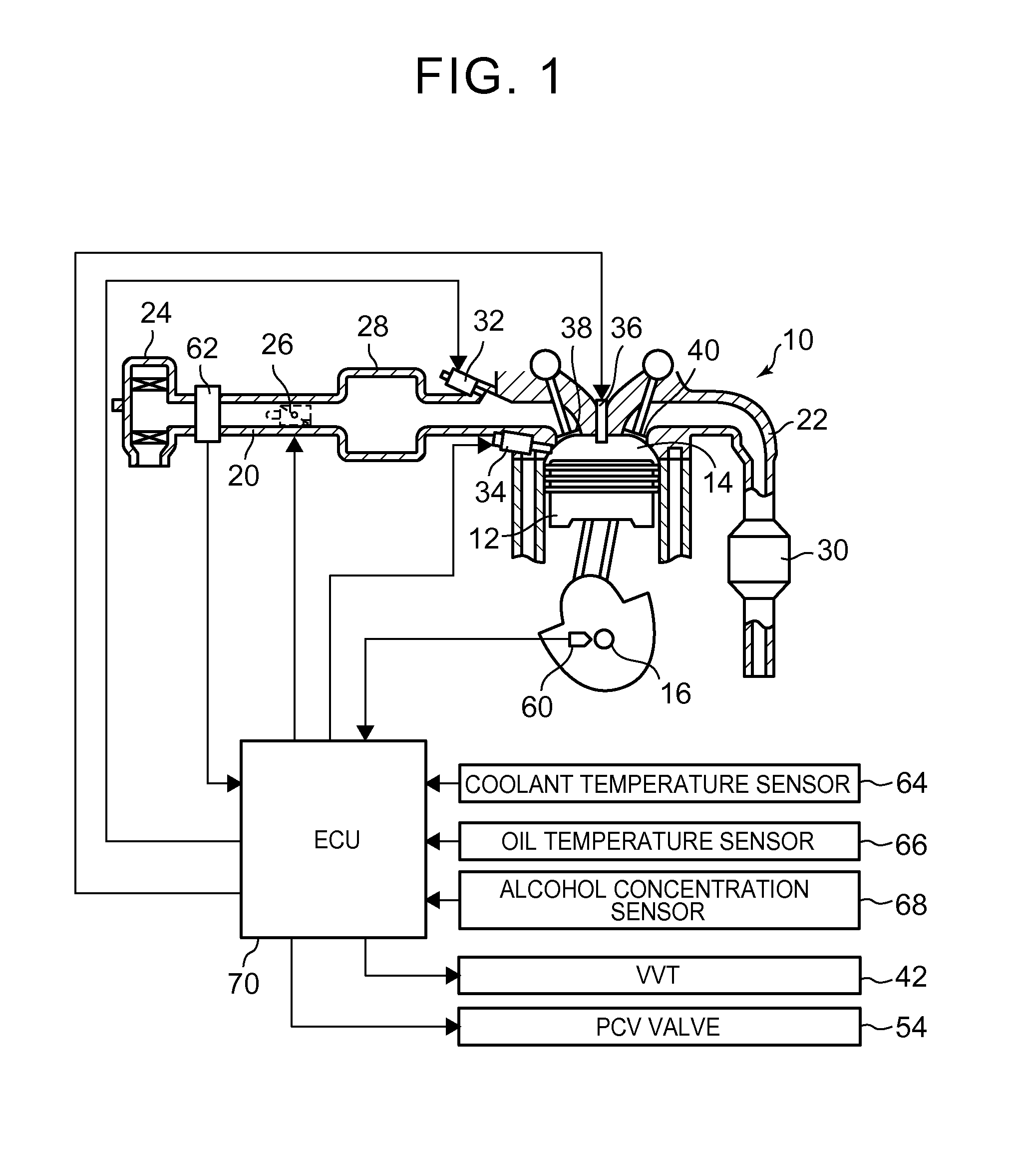
It is an object of this invention to restrain blow-by gas from reaching a catalyst during fuel cutoff, and protect the catalyst while coping with an increase in oil dilution amount resulting from the use of alcohol fuel, in an internal combustion engine that uses the alcohol fuel. An engine is equipped with a PCV mechanism that introduces blow-by gas in a crankcase into an intake system. Besides, when fuel cutoff is executed with the PCV mechanism in operation, an opening degree of a throttle valve during fuel cutoff is set on the basis of an oil dilution amount in lubricating oil. Thus, the throttle opening degree during fuel cutoff is adjusted in accordance with a generation amount of blow-by gas, so that an intake negative pressure can be appropriately reduced. Accordingly, during fuel cutoff, the amount of blow-by gas that is sucked out from the crankcase due to the intake negative pressure and introduced into the intake system can be held small.

Description

TECHNICAL FIELD[0001]The invention relates to a control apparatus for an internal combustion engine, and more particularly, to a control apparatus for an internal combustion engine that is endowed with a function of introducing blow-by gas in a crankcase into an intake system.BACKGROUND ART[0002]In recent years, the number of vehicles that can use alcohol fuel, such as flexible fuel vehicles (FFV's), tends to increase. In an internal combustion engine that uses alcohol fuel, the amount of fuel injection is larger and the volatility of fuel is lower than in an internal combustion engine that uses gasoline. Therefore, injected fuel is likely to adhere to an intake passage or a wall surface in a cylinder, and as a result, the amount of fuel that is mixed with engine oil (an oil dilution amount) also tends to increase. Accordingly, in the case where alcohol fuel is used, it is preferable to employ a PCV mechanism or the like.[0003]As disclosed in, for example, Patent Document 1 (Japanes...

Claims


Application Information

Patent Timeline
Patent Type & Authority Applications(United States)
IPC IPC(8): F02D41/00
CPCF02D41/003F02D41/123F02D19/084F02D41/0005F02D2250/08F02D2250/11F02M25/06F02D2041/001F01M13/00Y02T10/30Y02T10/40
Inventor TSUKAGOSHI, TAKAHIROMORITA, KOUJIFUJIWARA, TAKAHIKOMATSUDA, KAZUHISA
Owner TOYOTA JIDOSHA KK
Learn More