Surface Vibration Using Compliant Mechanical Amplifier

a technology of mechanical amplifier and surface vibration, applied in the field of mechanical amplifier, can solve the problems of loss during transmission through the structure, and achieve the effects of reducing drag, reducing the size of laminar separation bubble, and reducing drag

Inactive Publication Date: 2014-10-16
FLEXSYS
View PDF4 Cites 7 Cited by
  • Summary
  • Abstract
  • Description
  • Claims
  • Application Information

AI Technical Summary

Benefits of technology

[0047]It is additionally desired to achieve good low-frequency performance. This is achieved, in accordance with the invention, by designing a higher amplification arrangement having a lower natural frequency, which results in better low-frequency performance. Minimization of the effect of lower-order modes will afford improved consistence of the response.
[0049]Amplification devices of the type herein described have numerous applications, including without limitation, production of a surface vibration for improved flow over an airfoil surface; production of a surface vibration for eliminating ice that has formed on a wing; production of a surface vibration for acoustic purposes. Acoustic energy that has appropriately been phased can be used to dampen vibration of a surface. Also, an amplification device, as previously noted, can be loaded to absorb vibratory energy and thereby operate to isolate vibration, absorb energy, or otherwise function as a damper.
[0050]When applied to vibrate a surface, design characteristics and parameters that should be considered in the design of an amplification device include determination of the output force, output displacement, and frequency. Overall system frequency response will require determination of, and control over, system stiffness. The analysis, of course, requires that consideration be given to the input force, input displacement, and the frequency of the mechanical input signal. Also, package size, manufacturing methods, and material are evaluated with an eye toward minimizing power requirements and efficiency.
[0057]The ABLE system decreases drag significantly by reducing the size of the laminar separation bubble. More specifically, drag is reduced by as much as 70% by vibrating a membrane on the upper surface of the leading edge. Vibrating the entire airfoil surface and not just a membrane on the leading edge may have a similar effect. A small energy input yields large aerodynamic benefit. By way of illustration, a 70 mW input to the ABLE system can yield a 70% aerodynamic improvement (i.e., reduced drag, increased lift, improved uniformity of lift over the airfoil's range of motion, greater aerodynamic efficiency, etc.). In this regard, testing was conducted at University of Illinois Urbana-Champagne on a 12″ chord, 36″ span model, at Reynolds numbers of 60,000, 100,000, and 200,000.
[0058]From the standpoint of the manufacture of the compliant systems of the present invention, it is noted that the use of extrusion as a manufacturing technique yields good mechanical properties and a good surface finish. Additionally, the resulting product exhibits no oxidation and possesses high dimensional accuracy. In the practice of some embodiments of the invention, aluminum 2024 is targeted, with a minimum thickness of approximately 1 mm and a minimum corner / fillet of approximately 0.4 mm.

Problems solved by technology

However, some losses will occur during transmission through the structure 10 or device 11.

Method used


Image

  • Surface Vibration Using Compliant Mechanical Amplifier
  • Surface Vibration Using Compliant Mechanical Amplifier
  • Surface Vibration Using Compliant Mechanical Amplifier

Examples


Embodiment Construction

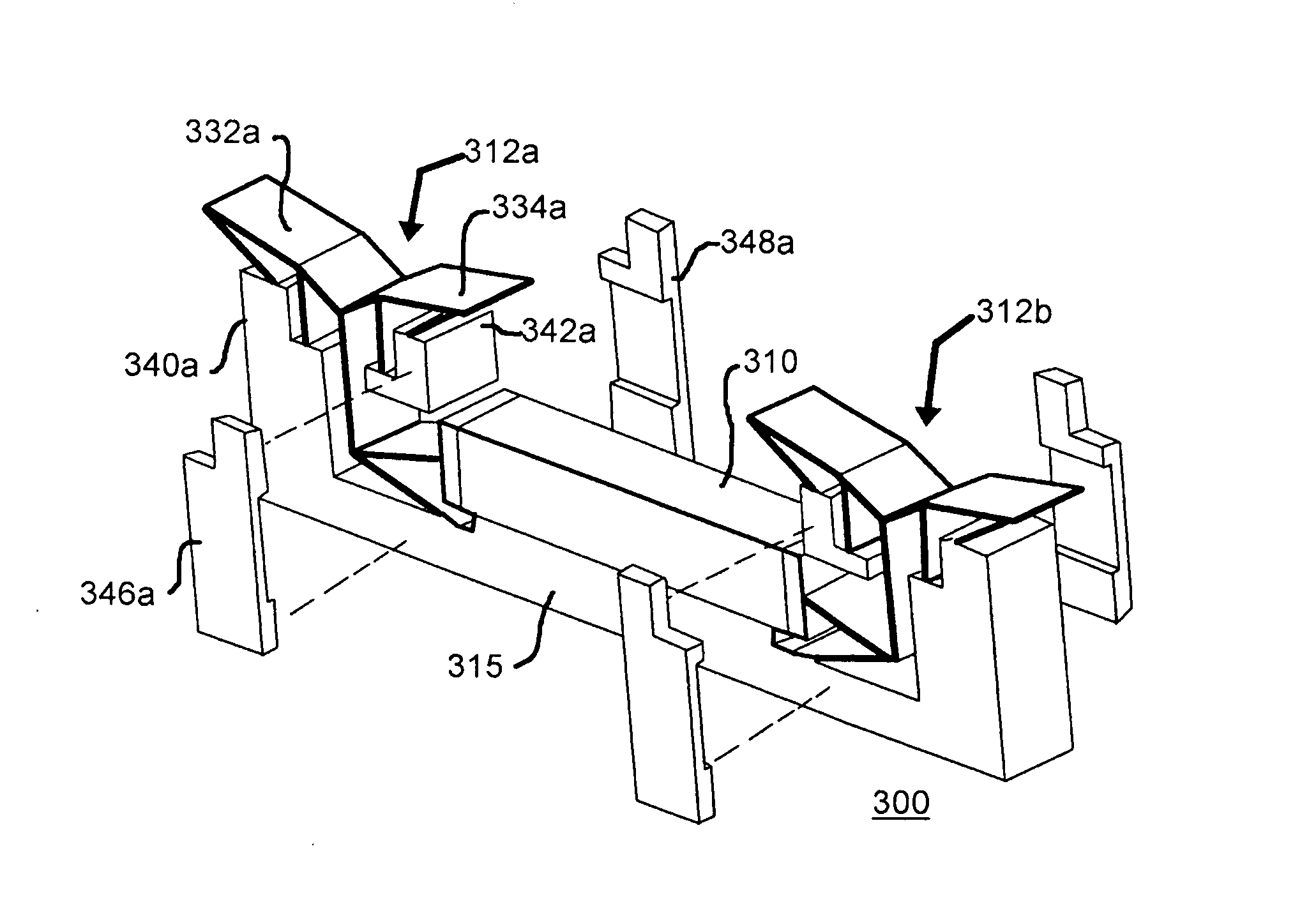
[0084]FIG. 5 is a simplified schematic representation showing a plan view of a specific illustrative embodiment of a compliant transducer arrangement 300 having a piezoelectric actuator 310 and symmetrical outputs 312a and 312b. FIG. 6 is an isometric representation of compliant transducer arrangement 300 shown in FIG. 5. As shown in these figures, compliant transducer arrangement 300 has a base 315 on which is installed piezoelectric actuator 310. The piezoelectric actuator is, in this specific illustrative embodiment of the invention, mounted longitudinally parallel to longitudinal axis 320 of base 315.

[0085]In this specific illustrative embodiment of the invention, symmetrical outputs 312a and 312b of compliant transducer arrangement 300 are mirror images of each other, and therefore the supporting structure of only symmetrical output 312a will be described in detail. As seen in FIG. 5, piezoelectric actuator 310 is coupled at its output to a compliant transducer structure 325a t...


PUM


Abstract

A displacement amplifier receives an actuation displacement signal from a piezoelectric actuator. The displacement signal is amplified by one or more stages of compliant elements, and a corresponding force is applied to a load. Wide frequency response is achieved in response to the resilience characteristics of the compliant elements that are formed from any of several materials, illustratively aluminum, steel, titanium, plastics, composites, etc., and are produced by any of several manufacturing techniques, illustratively extrusion, die casting, forging, etc. The compliant elements can be configured as plural compliant mechanical displacement amplifier stages. In bilateral arrangements displacement signals from distal ends of the motive source are applied to symmetrical, or mirror image, arrangements of compliant elements. The motive source, which may be a piezoelectric actuator, delivers its displacement signal at one end thereof to one or more compliant elements. The other end of the piezoelectric actuator can be grounded.

Description

CROSS-REFERENCE TO RELATED APPLICATIONS[0001]This application is a continuation of U.S. Ser. No. 12 / 450,796 filed on May 17, 2010 as the US national stage filing under 35 U.S.C. §371 of International Application No. PCT / US08 / 04871 filed on Apr. 14, 2008 and claims the benefit under 35 U.S.C. §119(e) of U.S. Provisional Patent Application Ser. No. 60 / 923,233 filed Apr. 13, 2007. The disclosures in these applications are incorporated herein by reference.BACKGROUND OF THE INVENTION[0002]1. Field of the Invention[0003]This invention relates generally to mechanisms that receive a displacement or force applied by an actuator and that deliver a modified displacement or force to a load, and more particularly, to a structure that employs elastically deformable elements that are coupled to each other generally without the use of pivot couplings and that deliver to the load a predetermined force / displacement characteristic.[0004]2. Description of the Prior Art[0005]There is known in the prior ...

Claims


Application Information

Patent Timeline
Patent Type & Authority Applications(United States)
IPC IPC(8): H02N2/00F16F7/00F16F15/00F16F15/04
CPCH02N2/001F16F15/005F16F7/00F16F15/04B64C3/48B64C23/06H02N2/043Y10T74/18856Y10T74/20564Y02T50/10
Inventor ERVIN, JAMES D.MARIC, DRAGANERVIN, GREGORY F.KOTA, SRIDHARHETRICK, JOEL A.
Owner FLEXSYS
Why Eureka
Try Eureka