Electric Motor

Active Publication Date: 2014-10-23
ROBERT BOSCH GMBH
View PDF2 Cites 0 Cited by
  • Summary
  • Abstract
  • Description
  • Claims
  • Application Information

AI Technical Summary

Benefits of technology

[0004]The electric motor according to the invention having the features of independent patent claim 1 and the fluid pump according to the invention having the features of independent patent claim 6 have the advantage, in contrast, that lubricant is introduced between the drive shaft and the bearing inner ring, which lubricant forms a hydrodynamic lubricant film and generates a constant relative movement between the drive shaft and the bearing inner ring. A permanent supply with introduced lubricant is thus advantageously ensured during the operation of the electric motor, as a result of which the drive shaft and the bearing inner ring have a constant slip. As a consequence, the hydrodynamic lubricant film makes a constant relative movement between the drive shaft and the bearing inner ring possible during the operation of the electric motor, whereby not only the radial loadings between the drive shaft and the bearing inner ring can be damped, but also a considerable n

Problems solved by technology

Said bearing arrangements frequently cause undesired nois

Method used


Image

  • Electric Motor
  • Electric Motor
  • Electric Motor

Examples


Embodiment Construction

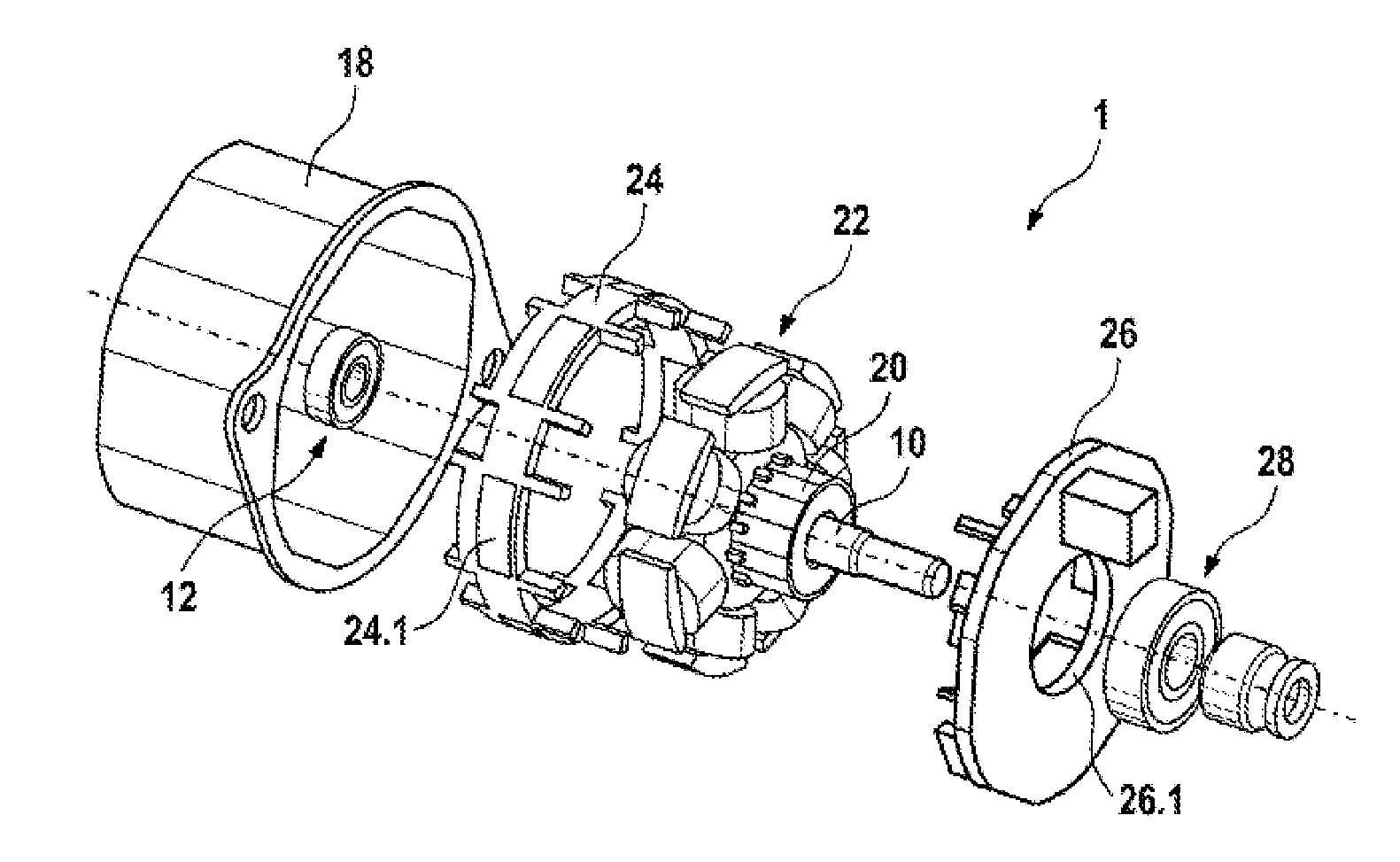
[0015]FIG. 1 shows an electric motor 1 according to the invention which can preferably be used as a drive for a hydraulic pump in a vehicle hydraulic system, even if embodiments of the electric motor 1 according to the invention can in principle also be used as drives for other vehicle systems.

[0016]As can be seen from FIG. 1, the electric motor 1 comprises an armature shaft 10 which is mounted rotatably in a floating bearing 12 within a cup-shaped pole casing 18. A commutator 20 which is arranged on the armature shaft 10 with an armature 22 and a magnet holder ring 24 with magnets 24.1 are accommodated in the pole casing 18. On the end side, a lid-shaped brush carrier 26 with a central aperture 26.1 for receiving the armature shaft 10 and a second bearing 28 covers the pole casing 18.

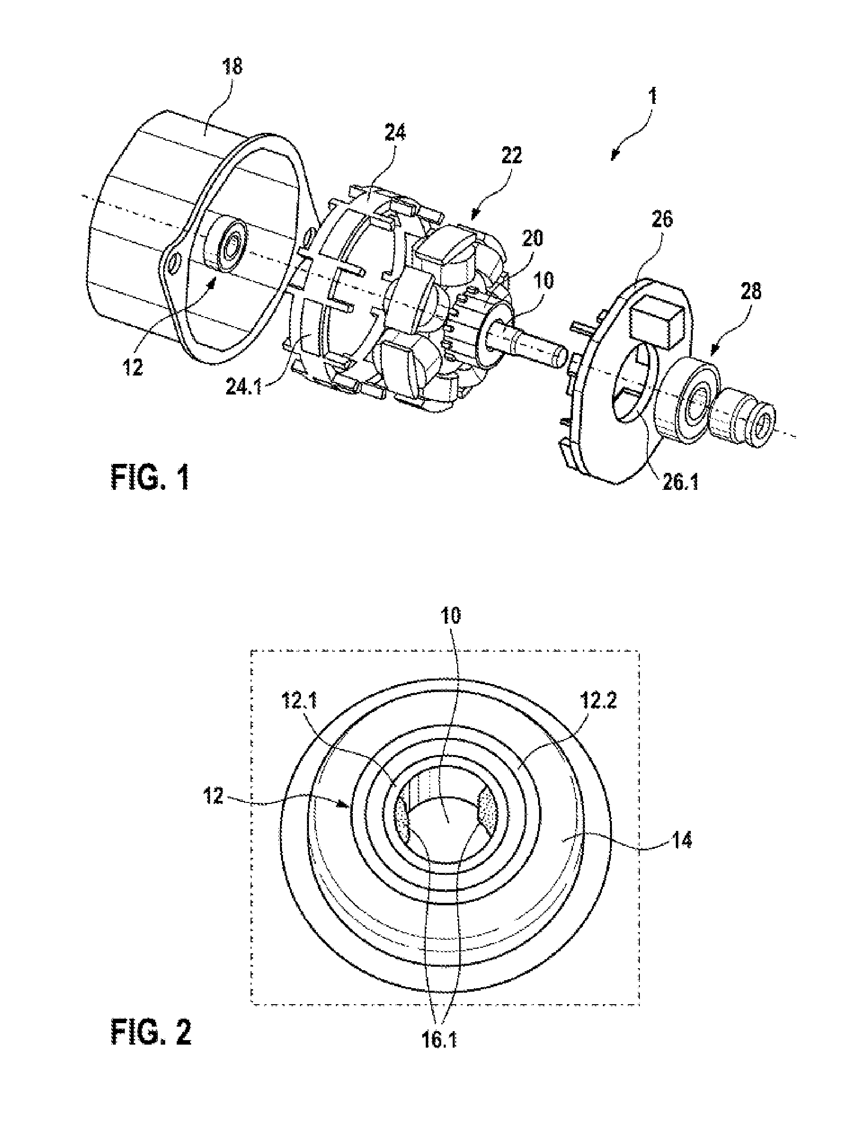
[0017]As can be seen from FIG. 2, the floating bearing 12 in the exemplary embodiment which is shown is configured as an antifriction bearing and, in addition to the rolling bodies, comprises a bearing...


PUM


Abstract

An electric motor includes an armature shaft which is mounted in at least one floating bearing. The floating bearing comprises a bearing inner ring, which is positioned on the armature shaft, a bearing outer ring, which is received in a bearing seat, and a fluid pump for a vehicle fluid system having the electric motor. Lubricant disposed between the armature shaft and the bearing inner ring forms a hydrodynamic lubricant film and generates a constant relative movement between the armature shaft and the bearing inner ring.

Description

PRIOR ART[0001]The invention proceeds from an electric motor in accordance with the preamble of independent patent claim 1.[0002]Electric motors of the abovementioned type are frequently used as a drive for hydraulic pumps in vehicle hydraulic systems, such as anti-lock brake systems (ABS) or traction control systems (ASR system) or electronic stability program systems (ESP system). Electric motors of this type comprise various bearing arrangements for mounting an armature shaft both in the radial and in the axial direction. Said bearing arrangements usually have both what are known as locating bearings and also what are known as floating bearings. Said bearing arrangements frequently cause undesired noise development during the operation of the electric motor.[0003]The laid-open specification DE 10 2006 042 340 A1 describes, for example, an electric motor with an armature shaft which is received in a bearing arrangement. Here, the armature shaft is mounted in at least one floating ...

Claims


Application Information

Patent Timeline
IPC IPC(8): F04B53/00F16C32/06
CPCF16C32/0629F04B53/001H02K5/1672F16C33/106F16C27/045F16C21/00F16C2380/26
Inventor MICKE, MARCFELLMETH, REINERKLEIN, STEFAN
Owner ROBERT BOSCH GMBH
Why Eureka
Try Eureka