Wave suppressor and sediment collection system for use in shallow and deeper water environments

a sediment collection system and shallow water technology, applied in the field of wave suppressor and sediment collection system, can solve the problems of loss of valuable coastline for states along the gulf of mexico, atlantic ocean and pacific ocean, and is susceptible to erosion, so as to suppress and effectively break down the energy of a wave

Active Publication Date: 2014-10-23
PIERCE JR WEBSTER
View PDF8 Cites 11 Cited by
  • Summary
  • Abstract
  • Description
  • Claims
  • Application Information

AI Technical Summary

Benefits of technology

[0030]It is a further principal object of the present invention to provide a system which will be constructed and applied in such a way as to have no adverse effect of the ecology of the environment the WSSC System is placed into.
[0031]It is a further object of the present invention to construct a device that could be used in deep water and would rest on or be integral to a large, raised base, so the device could suppress the energy of a wave in deeper water to effectively break down the energy in a wave; use the energy of the wave to help collect sediment; and use the energy of the wave to help rebuild coast...

Problems solved by technology

The loss of valuable coastline for states along the Gulf of Mexico, Atlantic Ocean and Pacific Ocean is a very serious problem.
However, with the loss of valuable marsh grass, the soil became susceptible to erosion, and consequently miles of valuable coastline were...

Method used


Image

  • Wave suppressor and sediment collection system for use in shallow and deeper water environments
  • Wave suppressor and sediment collection system for use in shallow and deeper water environments
  • Wave suppressor and sediment collection system for use in shallow and deeper water environments

Examples


first embodiment

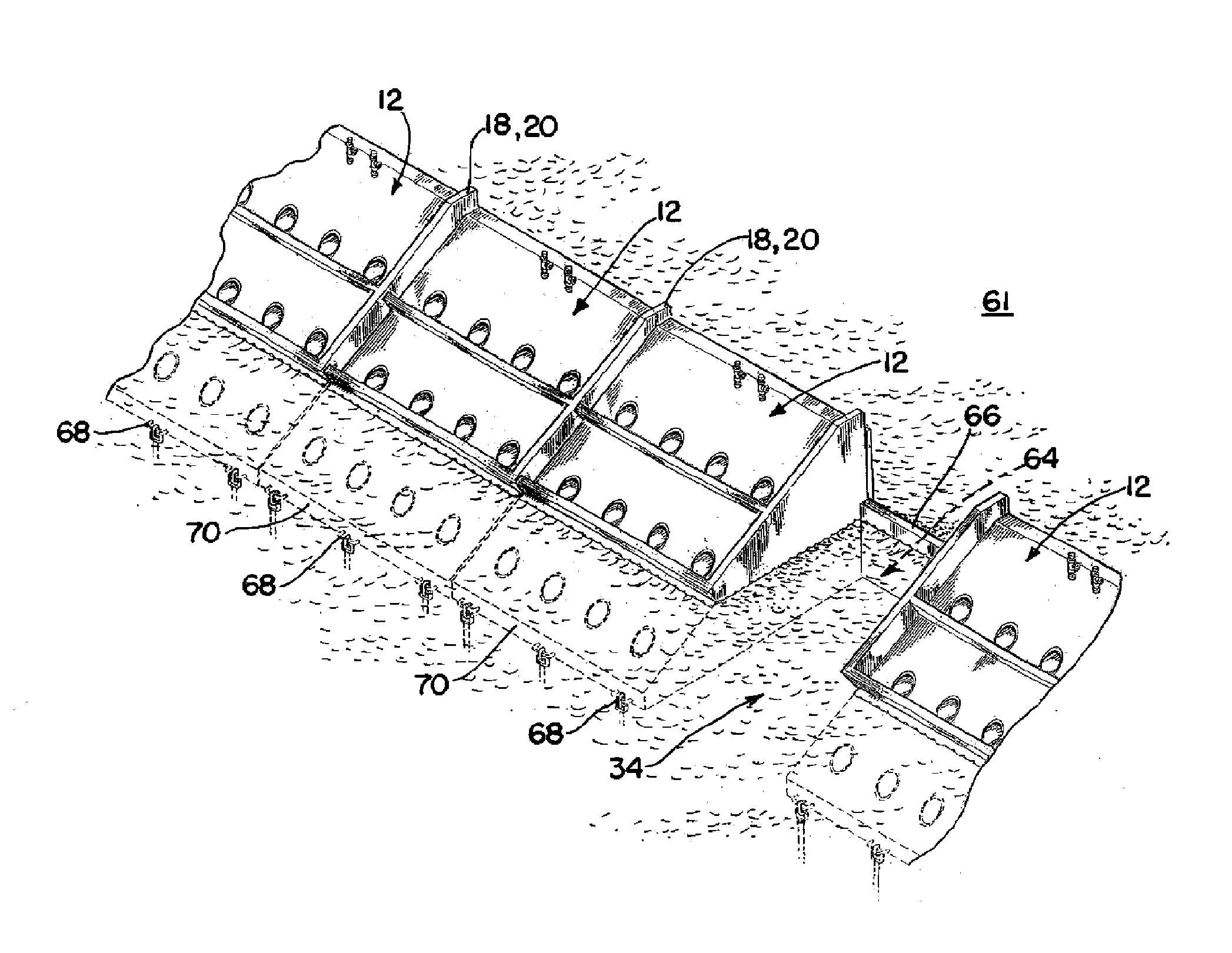
[0091]Reference is now made to FIGS. 18 through 24, where the WSSC System, labeled System 200 is incorporated into a rock jetty 150, of the type which has been constructed to block the entrance to the waterway referred to as Mr. Go in South Louisiana. As illustrated in top views in FIGS. 19 through 21, there is provided a rock jetty 150 into which the system 200 is incorporated. In FIG. 21, taken along lines 21-21 in FIG. 18, it is foreseen that the base 152 of the jetty 150 would be laid in place, and then a plurality of elongated pipes 202 would extend from the forward point 156 of jetty 150, in this case three pipe sections 202 to the rear point 158 of rock jetty 150. At the forward point 156, the three pipes 202 would extend from a trough 208, as illustrated in FIG. 24, having an upright rear wall 210, a angulated floor 212, and a pair of side walls 214, so that the trough 208 would serve to capture the flow or water 32 carrying sediment 34, and the angulated floor 212 would dir...

second embodiment

[0097]Reference is now made to FIGS. 26A-33C, which illustrate the WSSC System as it would be installed through a rock jetty 150 and will be illustrated as WSSC System 300.

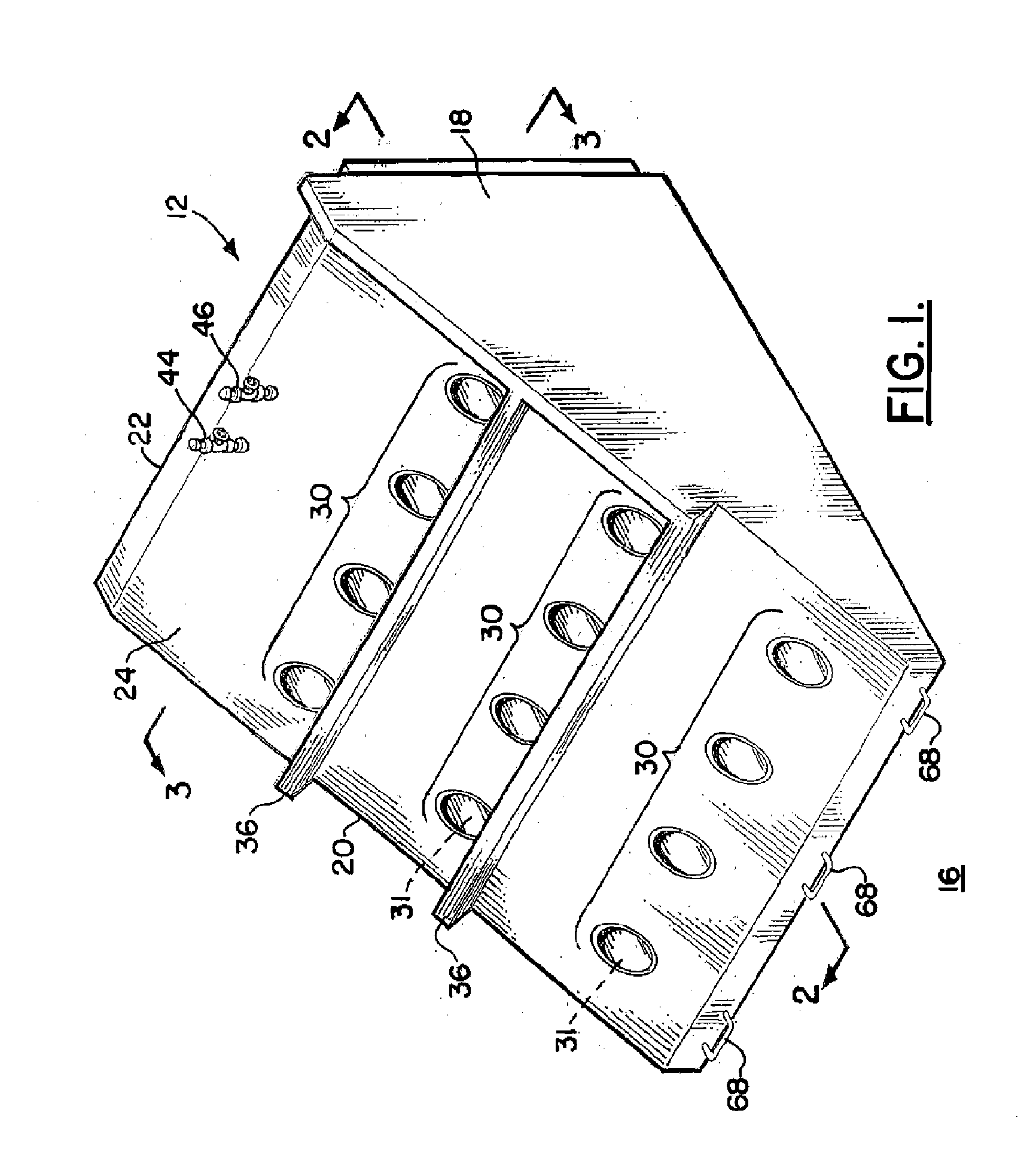
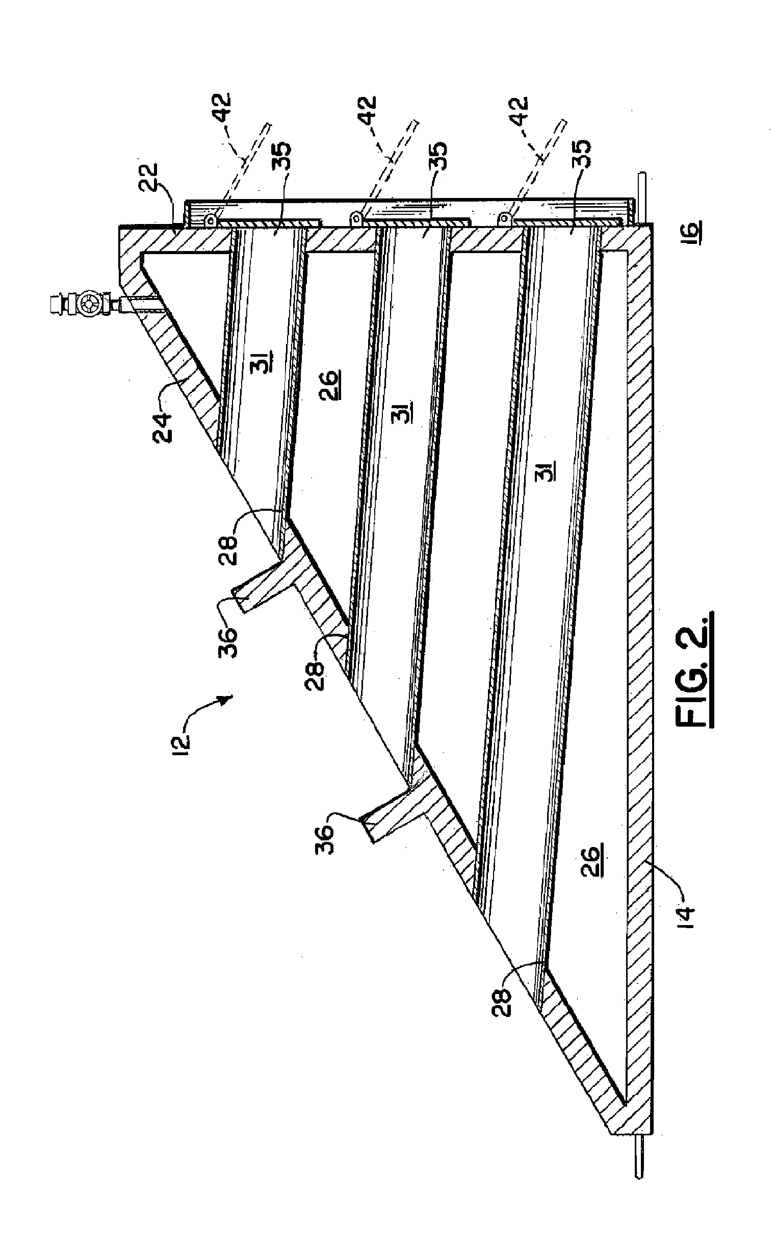
[0098]Turning now to FIGS. 26A and 26B, there is illustrated a body of water 60 having a current illustrated by arrows 65, flowing towards a rock jetty 150 as illustrated. In FIG. 27 there is a plurality of sediment collection components 302, which will be described below, positioned through the rock jetty 150 for the reasons as will be described further. As illustrated more clearly in FIG. 27, there is provided a single sediment collection component 302, extending through a rock jetty 150. The principal function of each of the components 302 is to receive water and sediment through the component 302 from the unprotected side 151 of the jetty 150 to the protected side 153 of the jetty 150 in order to enable sediment to be carried through the components 302 from the unprotected side 151 of the jetty 150, to the pro...


PUM


Abstract

A transportable wave suppressor and sediment collection (WSSC) system positionable in deep water along a coastline of a body of water, having a plurality of sections, each section further including a base portion having an upper floor portion, a forward wall, rear wall and two sidewalls and an open bottom end portion for being positioned on a floor of the body of water; at least a pair of raised elongated members positioned on the upper surface of the upper floor of the base; an upper portion to be secured to the base portion, the upper section having a angulated front wall to receive the flow of water through a plurality of flow pipes as the water engages each section; at least a pair of elongated openings in the upper portion for receiving the raised elongated members positioned on the upper surface of the upper wall of the base to define a means for securing the base to the upper portion. There is further provided a one way valving element positioned on the rear end of each flow pipe, for allowing water containing sediments to exit the pipe at the rear wall, but preventing the water and sediments from returning through the flow pipe; and a spacer portion to be positioned intermediate the base portion and upper portion, the spacer portion including a plurality of flow pipes to allow water carrying sediment to the rear of the section.

Description

CROSS-REFERENCE TO RELATED APPLICATIONS[0001]Priority of U.S. Provisional Patent application Ser. No. 61 / 772,368, filed on 4 Mar. 2013, which is hereby incorporated herein by reference thereto, is hereby claimed.[0002]This application is a continuation-in-part of U.S. patent application Ser. No. 13 / 554,202, filed on 20 Jul. 2012 (published as US2013 / 0022399 on 24 Jan. 2013), which is a continuation-in-part of U.S. patent application Ser. No. 12 / 576,359, filed on 9 Oct. 2009 (issued as U.S. Pat. No. 8,226,325 on 24 Jul. 2012) by the same inventor, each of which are hereby incorporated herein by reference thereto, and priority to each of which is hereby claimed.[0003]International Patent Application Serial No. PCT / US2010 / 052182, filed on 11 Oct. 2010 (published as No. WO2011 / 044556 on 14 Apr. 2011), is hereby incorporated herein by reference.STATEMENT REGARDING FEDERALLY SPONSORED RESEARCH OR DEVELOPMENT[0004]Not applicableREFERENCE TO A “MICROFICHE APPENDIX”[0005]Not applicableBACKGR...

Claims


Application Information

Patent Timeline
IPC IPC(8): E02B3/06
CPCE02B3/06E02B3/04E02B3/023E02B3/046E02B3/062E02B3/18
Inventor PIERCE, JR., WEBSTER
Owner PIERCE JR WEBSTER
Why Eureka
Try Eureka