Protective Sheath for Surgical Laser Fiber

a protective sheath and laser fiber technology, applied in the direction of surgery, medical science, surgical instrument details, etc., can solve the problems of reducing the flow of fluid through the working channel around the sheath/fiber assembly, and achieve the effect of preventing leakage from the working channel, convenient positioning, and convenient adjustmen

Inactive Publication Date: 2014-10-23
BROWN JOE DENTON
View PDF7 Cites 29 Cited by
  • Summary
  • Abstract
  • Description
  • Claims
  • Application Information

AI Technical Summary

Benefits of technology

[0011]A third improvement, which may also be used separately from or together with each of the first two improvements, is to provide visible markings on the sheath for use as trim indicators. Additionally, markings on the fiber will enable the physician to correctly and easily position the fiber just recessed within the tip of the sheath during insertion or removal of the sheath from the working channel of the introducer or scope. The markings on the fiber are not limited to a single set, but rather may include multiple sets at both the distal and proximal ends of the fiber that can be used in case it is necessary to re-strip the fiber. A fourth improvement is the addition of a sealing mechanism that allows the physician to lock the fiber's position relative to the sheath and also seals the pressurized zone inside the working channel from the unpressurized zone outside of the working channel thereby preventing leakage from the working channel. This sealing mechanism can take several forms. A Touhy-Borst connector that has a male Luer lock connector can be locked to the female Luer lock end of the universal connector provided with the shea

Problems solved by technology

Previous sheaths had the disadvantage of a relatively thick wall or larger outer diameter, causing fluid flow through the working channel around the sh

Method used


Image

  • Protective Sheath for Surgical Laser Fiber
  • Protective Sheath for Surgical Laser Fiber
  • Protective Sheath for Surgical Laser Fiber

Examples


Embodiment Construction

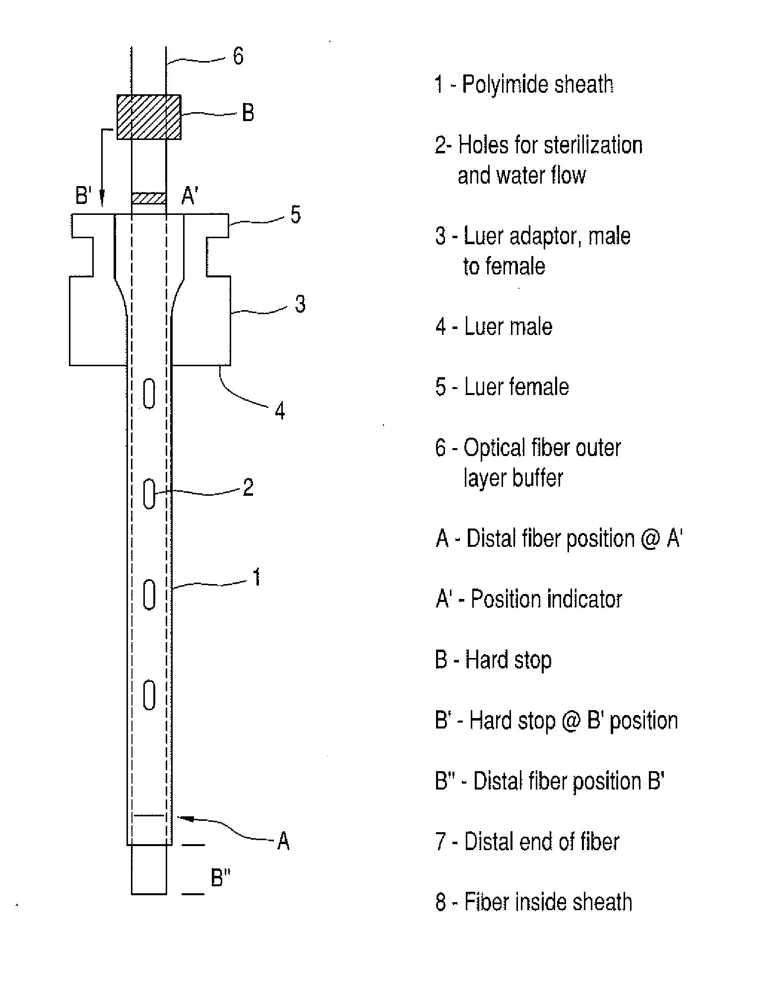
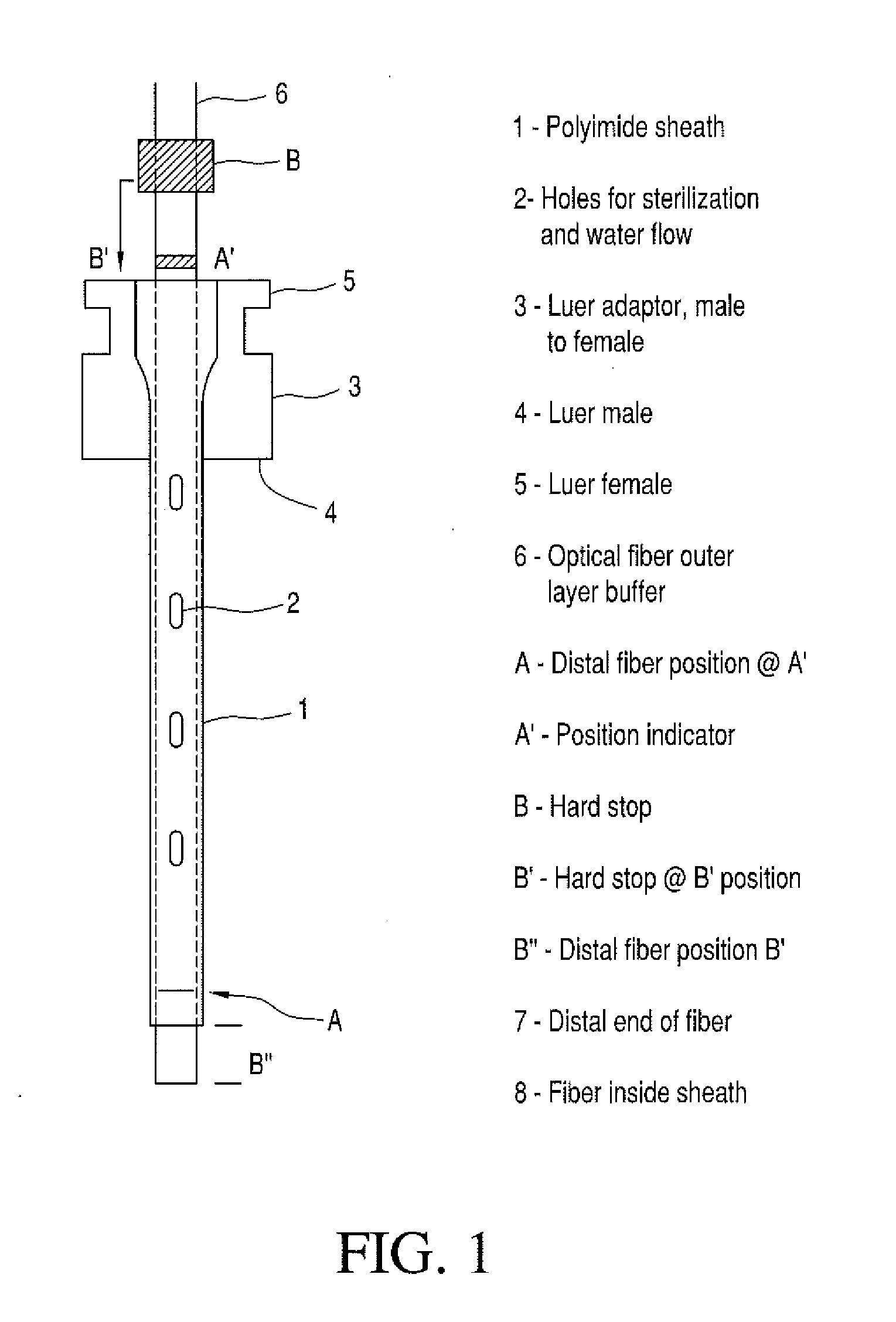
[0021]As shown in FIG. 1, the optical fiber buffer (6) is surrounded by a very thin-walled polyimide sheath (1) that performs several functions. The most important function of this sheath is to provide a protective sheath that allows the advancement of the relatively sharp-edged laser fiber tip through the ureteroscope without damaging the inner wall of the working channel, thereby preventing expensive repairs to the scope. Previous sheaths had such a thick wall and / or a large diameter that fluid flow through the working channel around the sheath / fiber assembly was greatly decreased, to the point where the physicians refused to use the sheath due to reduced vision due to reduced flow. The inner diameter (ID) of the sheath in this invention is very close to the maximum outer diameter (OD) of the buffer of the optical fiber (6) and the wall is very thin, thus providing maximum room for flow. Another design variation utilizes a larger ID that allows for the introduction of larger diame...


PUM


Abstract

A protective sheath of the type used to protect a scope during insertion of a fiber into the scope may include holes for improved fluid flow and for ease of sterilization, reinforcement, a luer connector to position the sheath relative to a scope and to enable use of a seal, pin vise or other device to secure the fiber to sheath during insertion or withdrawal of the sheath from the scope, and/or markings to facilitate positioning of the sheath relative to the scope and/or trimming of the fiber.

Description

[0001]This application claims the benefit of U.S. provisional patent application Ser. Nos. 61 / 824,755, filed May 17, 2013, 61 / 819,900, filed May 6, 2013, and 61 / 787,599, filed Mar. 15, 2013.BACKGROUND OF THE INVENTION[0002]1. Field of the Invention[0003]This invention relates to a device and method for delivering therapeutic light to a tissue, and in particular to an optical fiber arrangement in which a protective sheath is placed over the entire length of the fiber prior to insertion into an endoscope that guides the fiber to a treatment site. The protective sheath prevents mechanical damage to working channel of the endoscope during insertion of the fiber, insulates the fiber from surrounding cooling fluids, and may serve as an indicator of overheating that enables early detection of excess heating or burning of tissues or equipment at the treatment site.[0004]2. Description of Related Art[0005]The most important function of a protective sheath of the type with which the present i...

Claims


Application Information

Patent Timeline
IPC IPC(8): A61B18/24
CPCA61B18/24A61B2018/2205
Inventor BROWN, JOE DENTON
Owner BROWN JOE DENTON
Why Eureka
Try Eureka