
Visual Current Power Line

Inactive Publication Date: 2014-10-30
CAI XIANGXUAN
View PDF3 Cites 10 Cited by
  • Summary
  • Abstract
  • Description
  • Claims
  • Application Information

AI Technical Summary

Benefits of technology

This patent describes a new type of power line that can be used to power digital products like phones and computers. The power line has special electrodes that are coated with a layer of polyurethane coating containing polyisocyanate, which makes it strong and durable. The electrodes are arranged in a way that increases their hardness and wear resistance. This makes the power line better for use as a spotlight, and reduces the chances of unstable quality caused by touching wires. The polyurethane coating also helps to reduce processing costs and make the power line more competitive. Overall, this patent describes a new and improved power line that is more durable, efficient, and cost-effective.

Problems solved by technology

Existing power lines cannot display whether they are plugged in or whether they are at working.
In other words, by seeing from the outer surface of these power lines, we do not know whether they are at the working status of data transmitting or power charging.
The insulating medium on its metal baseline is a mixture of titanium dioxide and polyurethane, whose stickiness and insulation are too poor to achieve a satisfied aesthetics when it is used as the charging line of iphone4, HTC, Samsung mobile phone or other up-to-date electronic devices.
There are two auxiliary electrodes intertwining on the outer of the luminous core wire, and it requires a high processing cost to make such intertwining.
When the power line's outermost layer, namely the transparent plastic layer, is taken off for welding, the internal conductive layer will be completely exposed and may get in touch with other wires, resulting in an unstable quality and influencing the effect of electrical connection.

Method used


Image

  • Visual Current Power Line
  • Visual Current Power Line
  • Visual Current Power Line

Examples


Embodiment Construction

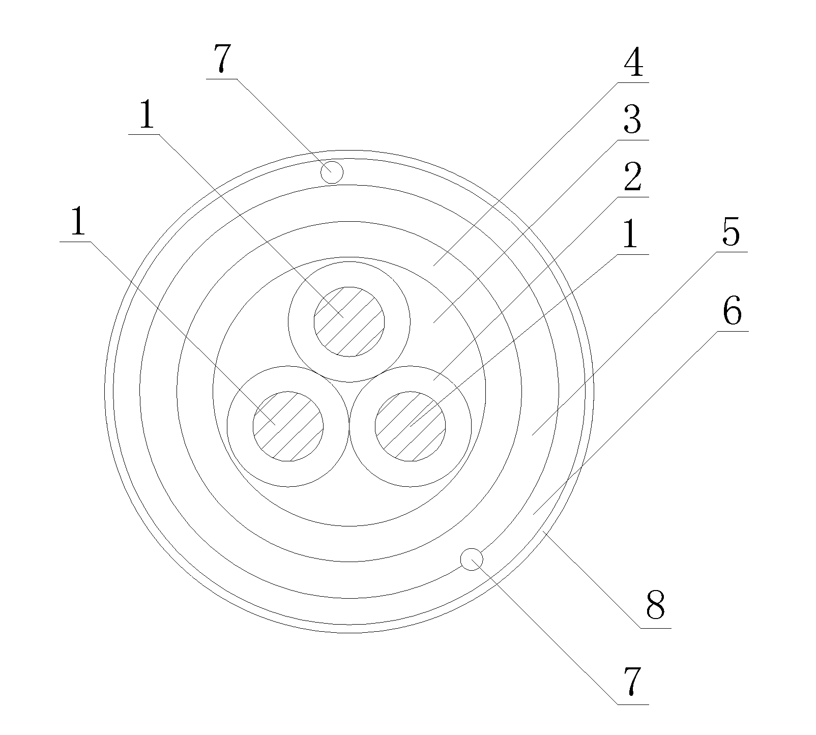
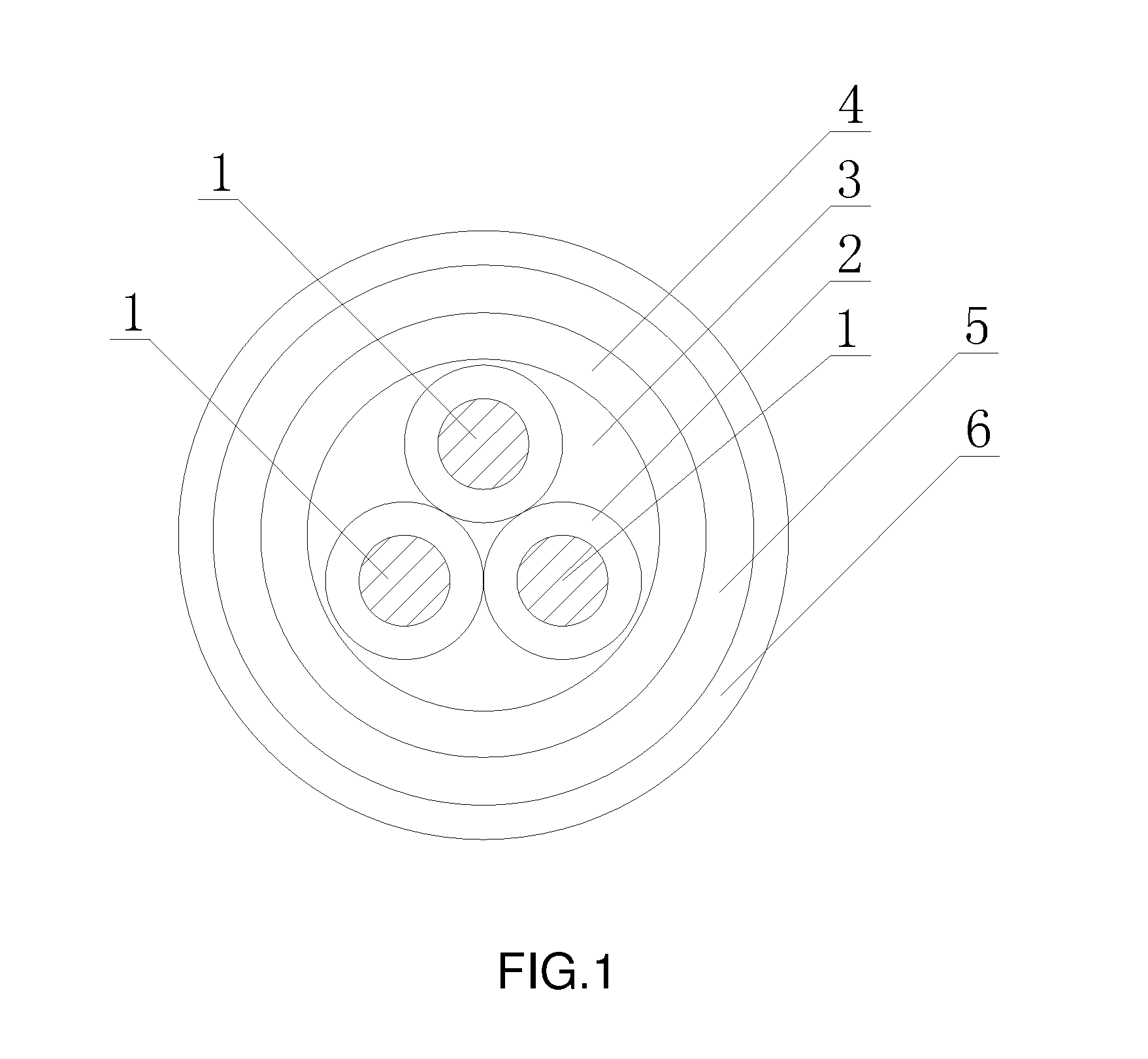
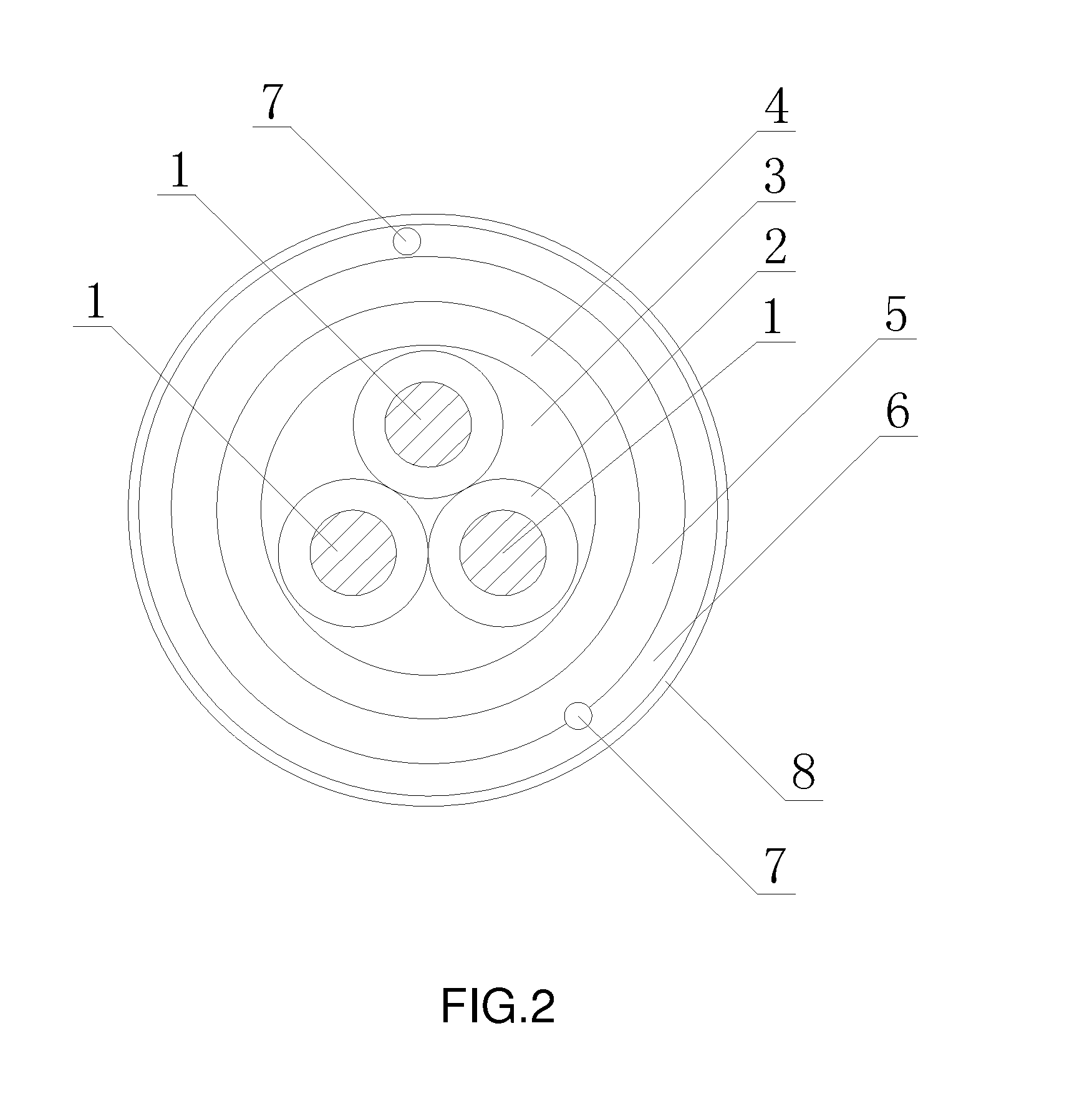
[0014]The invention will be further described in detail with the help of attached drawings and embodiments as follow.

[0015]As shown in FIGS. 1 and 2, the invention discloses a visual current power line, which contains one or more flexible center electrodes (1) that are sheathed by a luminous layer (4) and a light-pervious conducting layer (5) sequentially. The outer of each center electrode (1) is coated with an insulating layer (2), i.e. a polyurethane coating containing polyisocyanate. The center electrodes (1), jacketed with an insulating bush (3), are round wires with an outer diameter of 0.205-0.25 mm. The luminous layer (4) locates on the outer of the insulating bush (3), and the light-pervious conducting layer (5) is covered by a transparent plastic layer (6) printed with words and patterns. Outside of the transparent plastic layer (6), there is a color-changing plastic layer (8). Powder particles in the luminous layer (4) are wrapped up by transparent, insulating, and dielec...


PUM


Abstract

A visual current power line, which contains one or more flexible center electrodes that are sheathed by a luminous layer and a light-pervious conducting layer sequentially. The outer of each center electrode is coated with an insulating layer, i.e. a polyurethane coating containing polyisocyanate. The center electrodes, jacketed with an insulating bush, are round wires with an outer diameter of 0.205-0.25 mm. The luminous layer locates on the outer of the insulating bush, and the light-pervious conducting layer is covered by a transparent plastic layer, outside of which there is a color-changing plastic layer. Powder particles in the luminous layer are wrapped up by transparent, insulating, and dielectric thermoplastic polymer. The invention of current power line has features of good insulation, long life, low processing cost, reliable quality, large luminous area, and can be widely used in analogy, decoration, advertising, handicraft weaving and other fields of power or data lines.

Description

BACKGROUND OF THE INVENTION[0001]The invention belongs to cable product, specifically relating to a kind of power line with luminous display.[0002]Existing power lines cannot display whether they are plugged in or whether they are at working. In other words, by seeing from the outer surface of these power lines, we do not know whether they are at the working status of data transmitting or power charging. However, luminous core wire can be a good solution to this problem. The luminous core wire is made of a metal baseline, whose outer is wrapped or coated with an insulating dielectric layer, a luminous powder layer and a transparent conductive layer sequentially. When such luminous core wire is powdered on, it will luminesce to show its working status, adding dynamic new features to ordinary power lines.[0003]Applied on Aug. 19, 2005 and proclaimed for authorization on Jan. 19, 2011, the patent Piecewise-luminous Electroluminescent Cable, which obtains a patent No. 200510019319.X, di...

Claims


Application Information

Patent Timeline
IPC IPC(8): H01B7/02
CPCH01B7/0291H01B7/36H05B33/02H05B33/12
Inventor CAI, XIANGXUAN
Owner CAI XIANGXUAN
Features
  • Generate Ideas
  • Intellectual Property
  • Life Sciences
  • Materials
  • Tech Scout
  • Unparalleled Data Quality
  • Higher Quality Content
  • 60% Fewer Hallucinations
Learn More