Emergency lighting monitoring and reporting system

a technology of emergency lighting and monitoring system, applied in emergency power supply arrangements, instruments, sustainable manufacturing/processing, etc., can solve the problems of reducing the amount of stored energy in all types of batteries, labor-intensive manual inspection process, and reducing the light output. , to achieve the effect of reducing the light outpu

Active Publication Date: 2014-10-30
SIGNTEX
View PDF0 Cites 46 Cited by
  • Summary
  • Abstract
  • Description
  • Claims
  • Application Information

AI Technical Summary

Benefits of technology

[0027]The disclosure provides a central battery system that minimizes total maintenance costs over the life of the system by reducing the number of batteries required, and improving the means of access to batteries for service. The central battery system includes automated self testing capabilities and the ability to transmit data related to the self testing to a remote computer for compilation. The central battery system also can receive instructions from a remote location to change its operation parameters.
[0028]The disclosure provides emergency lighting fixtures that use LEDs (Light Emitting Diodes) having an operating life greater than conventional incandescent or fluorescent lamps. The fixtures also include specialized optics producing elongated beam patterns to reduce the total number of fixtures required to meet minimum light levels specified in LSC 101 along a linear path of egress, and specialized electronic circuits have been designed for these fixtures, to reduce the battery power required during emergency operation.
[0029]The disclosure provides a system that uses central batteries powering LED fixtures optimized for emergency lighting of egress pathways and automated self-test diagnostics with internet communication combined to produce the lowest possible life cycle costs with superior performance compared to conventional emergency lighting products. The disclosure provides a method of monitoring, testing, and reporting data about these systems to the users of the systems, the owners of the systems, and / or the authority having jurisdiction through Internet-based software.
[0031]The disclosure further provides a system for use with existing LED lighting fixtures that allows these existing fixtures to be used during emergency lighting operations. In one configuration, a control module is associated with each LED fixture and communicates with the dimming function of the LED fixture to reduce the light output of the LED fixture during an emergency lighting situation. The control module can test the lighting fixture for operable function and communicate the test result back to the central battery system through power line communication.

Problems solved by technology

Given the number of fixtures required in typical commercial and industrial buildings, a manual inspection process meeting the requirements for the four tests identified above is labor intensive.
Completion of these tests and reports is an onerous procedure and is rarely accomplished correctly or completely by facility or maintenance managers.
Over time, the amount of stored energy in all types of battery will decrease, to the point when a fully charged battery is no longer able to meet the minimum power requirements for emergency operation, and they must then be immediately replaced.
While these solutions may help the facility manager to identify equipment with bad lamps or batteries, they are expensive to install and do nothing to reduce the cost of replacing components found to be faulty, which is by far the largest portion of total maintenance expense.
Replacement of batteries and lamps in unit equipment is labor intensive because each fixture with a failed component must be accessed (most often requiring a ladder or a portable lifting system for fixtures in high locations), dismantled, have wiring disconnected, the battery, lamps or other components of the charging mechanism or the transfer switch replaced with new components, followed by reconnection, reassembly and testing.
In addition, typical batteries or emergency ballasts are manufactured specifically for the fixture and are thus not readily available as a stock item from electrical distributors; they must be carefully identified by part number and purchased direct from the factory or through a specialized supply service.
As described, total cost for routine maintenance of unit equipment for any facility can be substantial, especially in cases where large quantities of fixtures are installed.
The converter circuits are relatively complex and especially in larger machines, expensive.
Because of the inherent danger associated with high DC voltages and complex wiring schemes, manufacturers of such equipment usually require installation and setup by factory trained mechanics.
Typical fixtures connected to inverters are designed for general lighting under normal conditions and as such, the lumen output, lamp power and beam spread patters are not optimized for emergency lighting.
General lighting fixtures with multiple lamps can be configured to operate with a reduced number of lamps for emergency operation, thus saving battery energy, but that cannot be done with single-lamp fixtures.
As a result, general lighting fixtures operate at higher power than is required by the Code, requiring larger, more expensive batteries compared to a central power system for fixtures designed specifically for emergency lighting.

Method used


Image

  • Emergency lighting monitoring and reporting system
  • Emergency lighting monitoring and reporting system
  • Emergency lighting monitoring and reporting system

Examples


Embodiment Construction

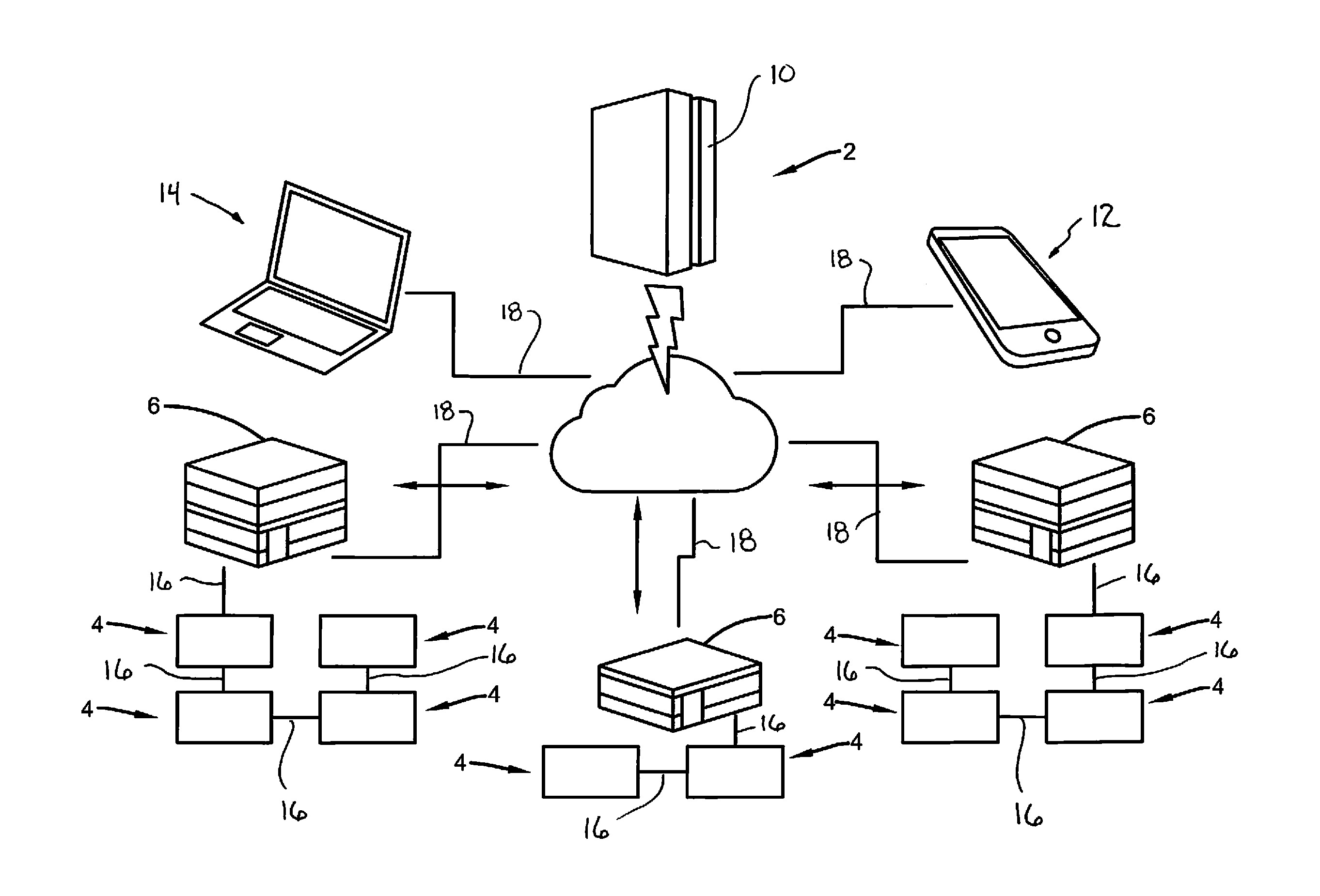
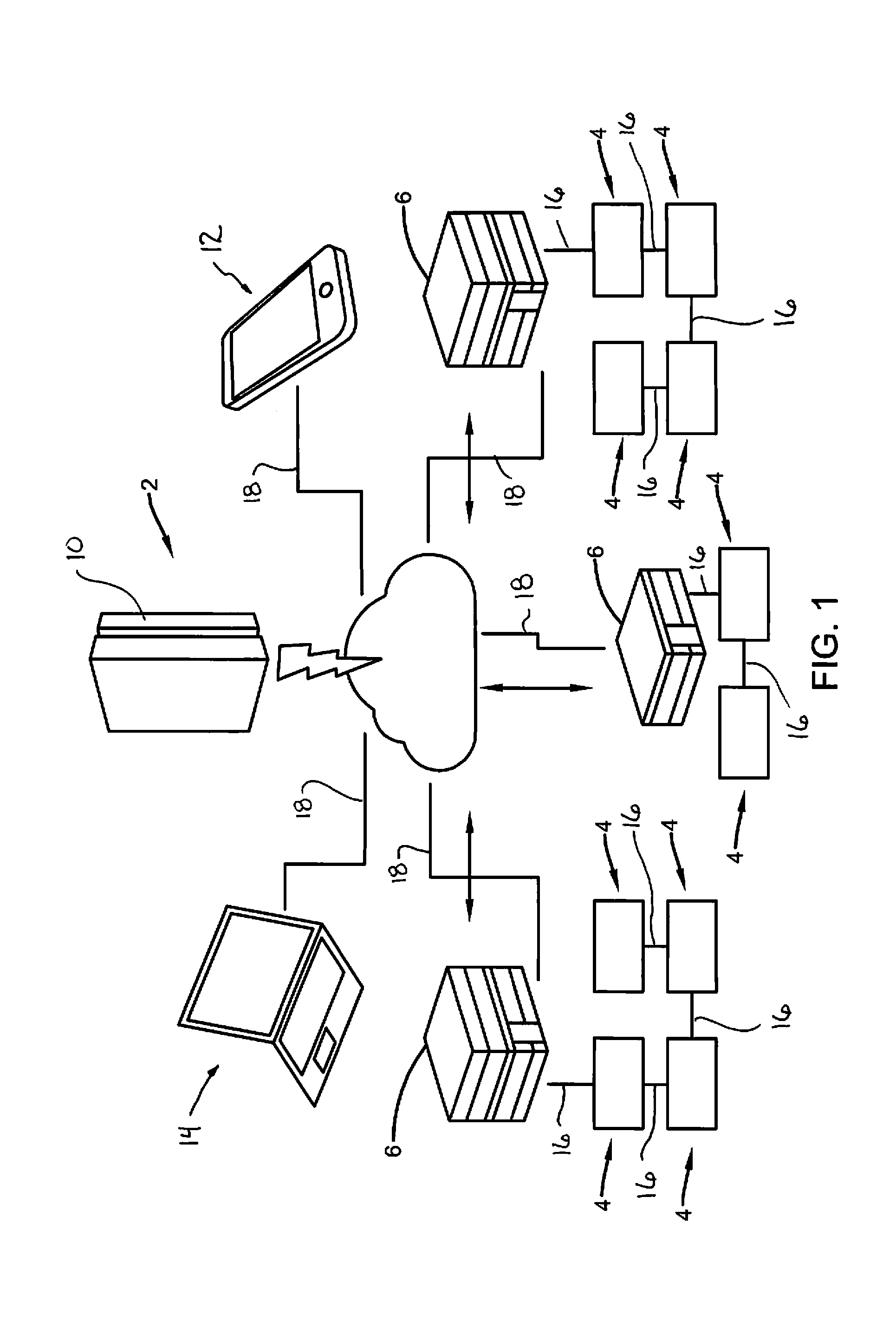
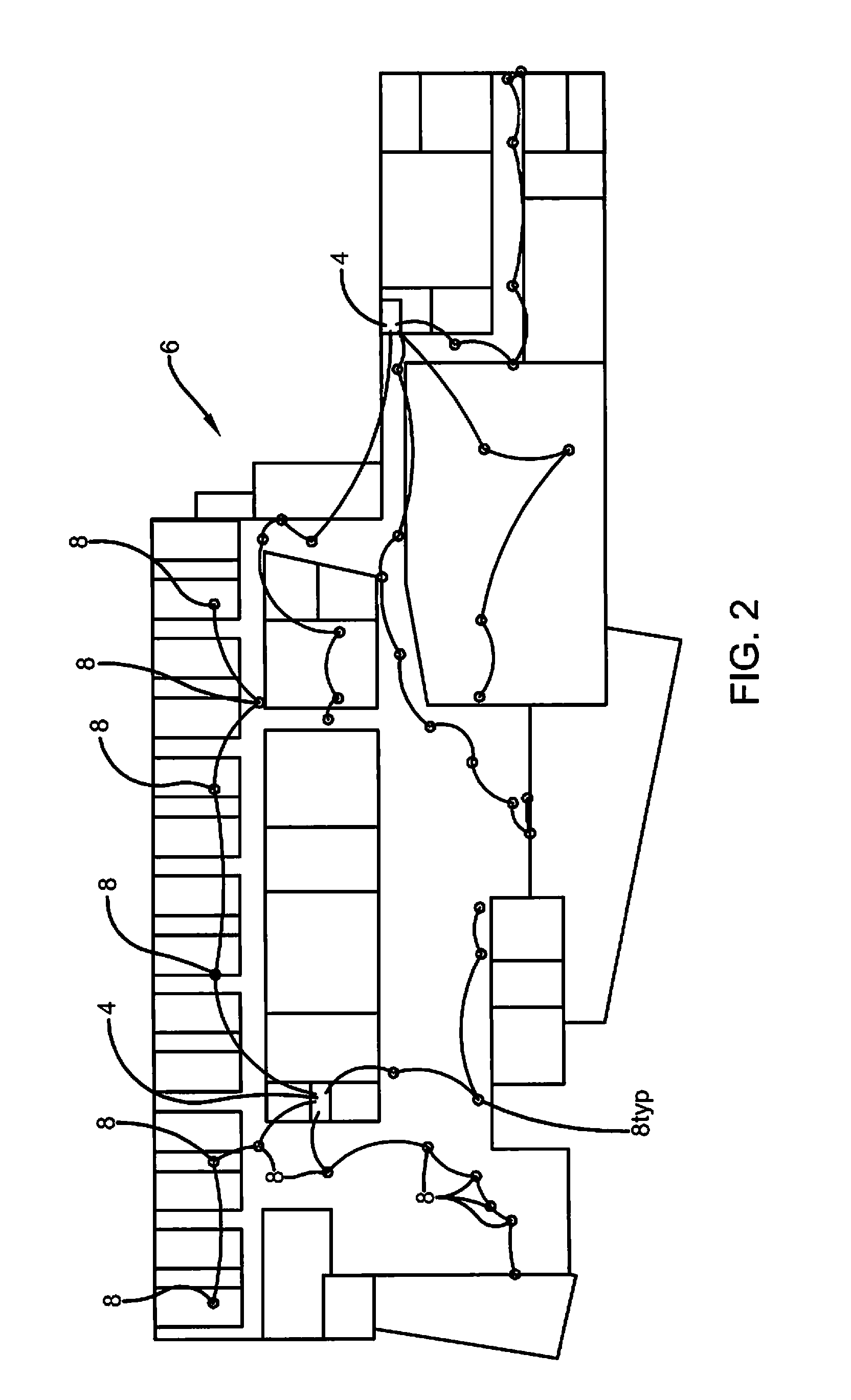
[0038]An exemplary emergency lighting monitoring and reporting system 2 includes a plurality of central battery systems 4 located in different buildings 6. Buildings 6 may be geographically distant or geographically together at a common campus. Buildings 6 may be commonly owned or owned by different entities. Each central battery system 4 provides normal on and backup power to at least one but typically a plurality of lighting circuits that each may include a plurality of lighting fixtures 8. Lighting fixtures 8 are emergency lighting fixtures that require a battery backup power so they may be used to provide lighting during power outages. As described above, such battery backup systems must be tested periodically and reports must be available for the AHJ. Each central battery system 4 is adapted to perform the testing and data reporting functions that allow the user of the lighting systems to comply with the requirements of the AHJ. Central battery systems 4 provide the power, test...


PUM


Abstract

An emergency lighting system with central batteries power remote LED fixtures and exit signs, with all components integrated throughout a single or multiple buildings. Status reports are available on demand and the system will generate written records required by the Life Safety Code. A wide range of fixtures optimized for emergency lighting are available for interior and exterior applications and all can be monitored via internet, with report displays available on any digital device. Easy access to batteries, automated testing, high lumen outputs, efficient optics and long lamp life ensure the lowest possible life cycle costs.

Description

CROSS REFERENCE TO RELATED APPLICATIONS[0001]This application claims the benefit of U.S. Provisional Patent Application Ser. No. 61 / 817,138 filed Apr. 29, 2013. This application also claims the benefit of U.S. Provisional Patent Application Ser. No. 61 / 976,249 filed Apr. 7, 2014. The disclosures of both are incorporated herein by reference.BACKGROUND OF THE DISCLOSURE[0002]1. Technical Field[0003]The disclosure relates to lighting systems with backup power supplies and, more particularly, to emergency lighting systems with centralized backup power, periodic testing systems and methods, and reporting and monitoring systems and methods.[0004]2. Background Information[0005]Emergency lighting products in the USA and other countries are required to be installed in all commercial, industrial and other buildings with public access. Regulations controlling operation and performance of emergency lighting products in the USA are published by the National Fire Protection Association Life Safet...

Claims


Application Information

Patent Timeline
Patent Type & Authority Applications(United States)
IPC IPC(8): H05B37/03G09F13/04H02J9/06H05B44/00
CPCH05B37/03G09F13/04H02J9/061H02J9/02H05B47/20Y02P80/10H05B45/10F21S8/02G01R31/367Y02B20/40G09F13/22G09F2013/222H02J7/0068H02J9/062
Inventor HEGARTY, WILLIAM
Owner SIGNTEX
Why Eureka
Try Eureka