Electronic lateral flow test arrangement and method

a technology of lateral flow and electrodes, applied in the direction of nucleotide libraries, instruments, library screening, etc., can solve the problems of large change in capacitance, physical layout, and difficulty in providing electrodes on the opposite side of the test strip, and achieve high porosity and high volume flow rate

Active Publication Date: 2014-10-30
NXP BV
View PDF14 Cites 12 Cited by
  • Summary
  • Abstract
  • Description
  • Claims
  • Application Information

AI Technical Summary

Benefits of technology

[0012]In embodiments, the test strip comprises a membrane with a porosity between 66% and 84% by volume. This is typical for readily available nitrocellulose membrane; however, other membranes with a porosity of up to, or even over, 96% may also be used. A high porosity allows for a high volume flow rate laterally along the test strip, since there is little impedance to flow.

Problems solved by technology

Accumulation of marker molecules in the test region then may alter the permittivity of the material directly between the electrodes—that is to say, the capacitor conductive plates—and cause a relatively larger change to the capacitance, compared with the arrangement where both electrodes are on the same side of the strip, although the physical layout, to provide the electrodes on opposite sides of the test strip may be more complex.

Method used


Image

  • Electronic lateral flow test arrangement and method
  • Electronic lateral flow test arrangement and method
  • Electronic lateral flow test arrangement and method

Examples


Embodiment Construction

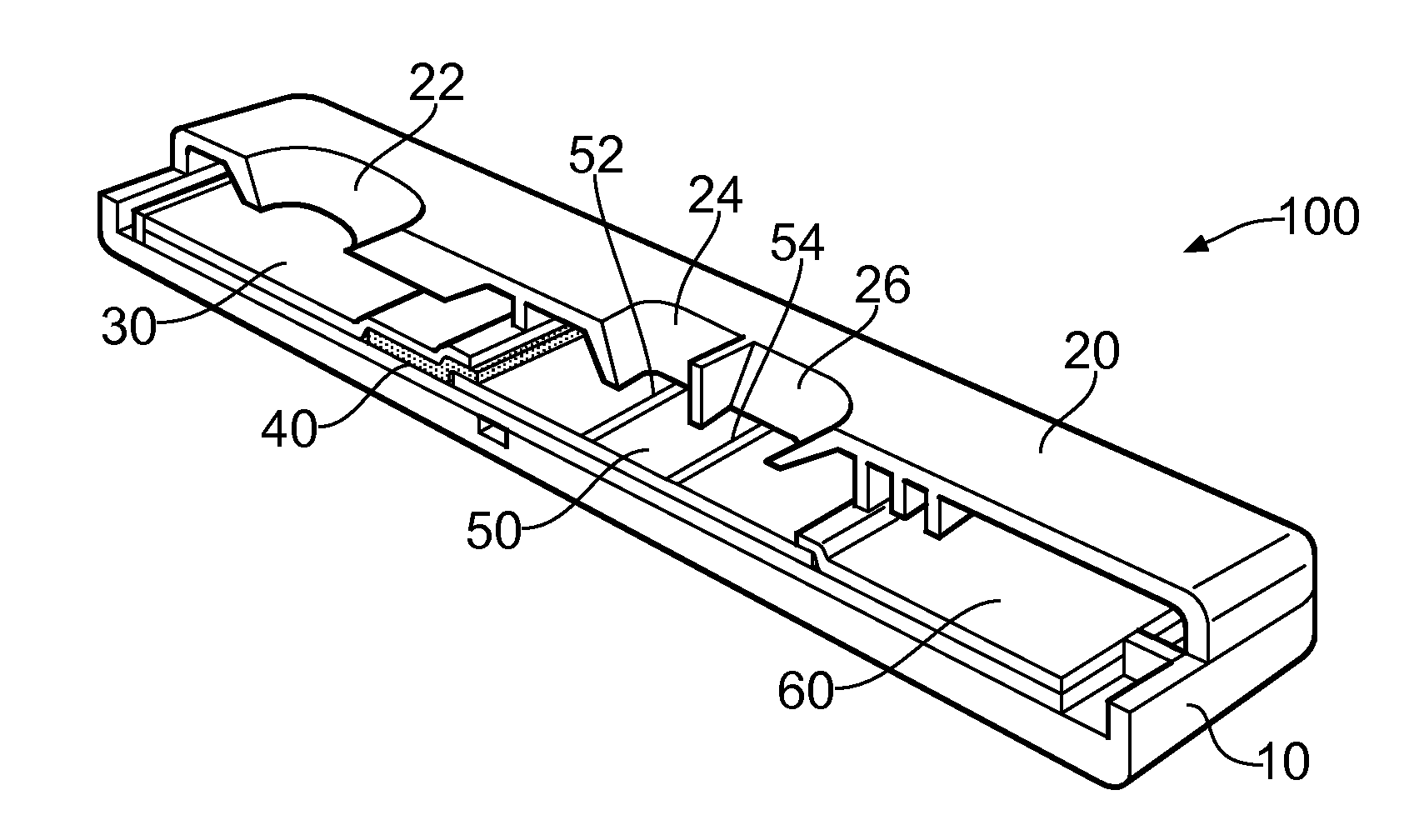
[0032]FIG. 1 shows a cutaway schematic of a conventional lateral flow test device 100. The device has a bottom housing 10, and a top housing 20 shown longitudinally cutaway. The top housing 20 has three ports therein. The first port 22, positioned towards one end of the arrangement, is a sample port, whereby a sample fluid such as urine may be introduced into the device. The other two ports 24 and 26 are positioned remote from the sample port 22, and are for viewing test results as will be described hereinbelow. Inside the device there is a sample pad 30 for receiving the sample introduced into the device through sample port 22. In contact with the sample pad 30 is a conjugate pad 40. The conjugate pad 40 is impregnated with conjugate molecules. In turn, the conjugate pad 40 is in contact with a test strip 50, which takes the form of a membrane. The test strip is an elongate strip which may typically be 5 mm or 3 mm in width and between 5 cm and 15 cm in length and extends generally...


PUM

PropertyMeasurementUnit
widthaaaaaaaaaa
porosityaaaaaaaaaa
porosityaaaaaaaaaa

Abstract

A lateral test flow arrangement for a test molecule is disclosed, comprising: a test strip for transporting an analyte away from a sampling region and towards an absorbing region, the test strip having therein and remote from the sampling region, a test region for functionalization with a molecule which binds to the test molecule or to a conjugate of the test molecule; a sensing test capacitor having electrodes extending across the test strip at least partially aligned with the test region and being physically isolated therefrom; a reference test capacitor having electrodes extending across the test strip and being physically isolated therefrom; and an electronic circuit configured to measure a time-dependant capacitance difference between the sensing test capacitor and the reference test capacitor. A method for carrying out that lateral flow tests is also disclosed, as are test systems and in particular pregnancy test systems

Description

FIELD OF THE INVENTION[0001]This invention relates to lateral flow test arrangements and to methods of carrying out lateral flow tests. It also relates to test systems, such as for example pregnancy test systems.BACKGROUND OF THE INVENTION[0002]A conventional lateral flow test apparatus comprises an elongate membrane along which a sample analyte flows. The sample analyte may or may not contain a test molecule at a concentration level of interest. Typically, at a specific test region, the membrane is impregnated with molecules which are chosen because they interact either with the test molecule, or with a marker molecule which may be conjugated with the test molecule. The impregnated molecules are typically bioreceptors. The presence of the test molecule in the sample analyte, at or above the concentration level of interest, results in an accumulation of the markup at the test line. Provided the marker is optically active, once a sufficiently high concentration of markers has accumul...

Claims


Application Information

Patent Timeline
Patent Type & Authority Applications(United States)
IPC IPC(8): G01N33/68G01N33/543G01N33/558
CPCG01N33/689G01N33/5438G01N33/558G01N27/22G01N27/3274G01N33/54388
Inventor NGUYEN, VIETWIDDERSHOVEN, FRANCISCUS PETRUSDAAMEN, ROEL
Owner NXP BV
Why Eureka
Try Eureka