Image pickup panel and image pickup processing system
- Summary
- Abstract
- Description
- Claims
- Application Information
AI Technical Summary
Benefits of technology
Problems solved by technology
Method used
Image
Examples
first embodiment
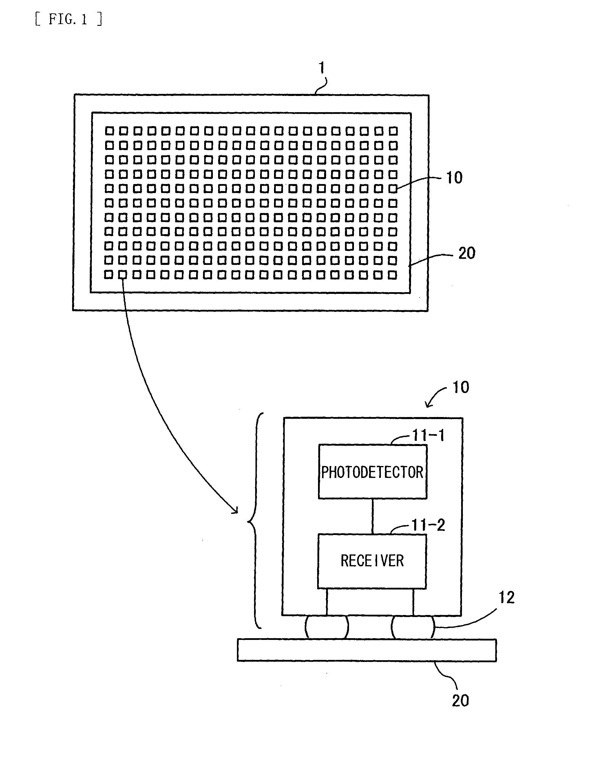
[0106]Next, a configuration of the image pickup panel 1 will be described below. FIG. 13 is a diagram illustrating a configuration example of the image pickup panel. An image pickup panel 1-1 includes a plurality of photodetection sections 10 (photodetection sections 10-1 to 10-9 in the drawing) and the wiring layer 20, and further includes a scintillator 31, a cover glass substrate 32, and a wiring-side glass substrate 33.
[0107]The photodetection sections 10-1 to 10-9 are FC bonded on the wiring layer 20. Moreover, the scintillator 31 is so disposed as to cover all of light-receiving surfaces of the photodetection sections 10 arranged on the wiring layer 20. It is to be noted that the scintillator 31 is a fluorescent medium converting incident radiation rays (for example, X-rays) into light to emit the light.
[0108]The cover glass substrate 32 is disposed on a top surface of the scintillator 31, and covers and protects the scintillator 31. Moreover, the wiring-side glass substrate ...
second embodiment
[0117]FIG. 14 is a diagram illustrating a configuration example of the image pickup panel. An image pickup panel 1-2 includes a plurality of photodetection sections 10 (the photodetection sections 10-1 to 10-9 in the drawing) and the wiring layer 20, and further includes a scintillator 41, a PET (Polyethylene Terephthalate) substrate 42, and a heat-resistant resin substrate 43.
[0118]It is to be noted that the PET substrate 42 and the heat-resistant resin substrate 43 both have flexibility, and the PET substrate 42 corresponds to a first flexible substrate, and the heat-resistant resin substrate 43 corresponds to a second flexible substrate.
[0119]The photodetection sections 10-1 to 10-9 are FC bonded on the wiring layer 20. Moreover, the scintillator 41 is so disposed as to cover all of the light-receiving surfaces of the photodetection sections 10 arranged on the wiring layer 20.
[0120]The PET substrate 42 is disposed on a top surface of the scintillator 41, and covers and protects ...
third embodiment
[0133]FIG. 15 is a diagram illustrating a configuration example of the image pickup panel. An image pickup panel 1-3 includes a plurality of photodetection sections 10 (the photodetection sections 10-1 to 10-9 in the drawing) and the wiring layer 20, and further includes the scintillator 41, the PET substrate 42, and the heat-resistant resin substrate 43.
[0134]The image pickup panel 1-3 has the same basic configuration as the image pickup panel 1-2 according to the second embodiment. The image pickup panel 1-3 is different from the image pickup panel 1-2 in that, after the photodetection sections 10-1 to 10-9 are FC bonded on the wiring layer 20, transparent resins 44-1 to 44-9 are formed on the photodetection sections 10-1 to 10-9 by a potting process (a resin potting process) with use of, for example, a high-speed dispenser to seal the photodetection sections 10-1 to 10-9, respectively.
[0135]The transparent resins 44-1 to 44-9 to have a lens effect through potting the photodetect...
PUM
 Abstract
Description
Claims
Application Information
 - R&D
- Intellectual Property
- Life Sciences
- Materials
- Tech Scout
- Unparalleled Data Quality
- Higher Quality Content
- 60% Fewer Hallucinations
Browse by: Latest US Patents, China's latest patents, Technical Efficacy Thesaurus, Application Domain, Technology Topic, Popular Technical Reports.
© 2025 PatSnap. All rights reserved.Legal|Privacy policy|Modern Slavery Act Transparency Statement|Sitemap|About US| Contact US: help@patsnap.com


