Power converter

a technology of power converter and converter, applied in the direction of power conversion system, ac-ac conversion, electrical apparatus, etc., can solve the problems of complex control circuit and inability to utilize the features of capacitorless method, and achieve good responsivity to inductive load

Active Publication Date: 2014-11-06
DAIKIN IND LTD
View PDF4 Cites 24 Cited by
  • Summary
  • Abstract
  • Description
  • Claims
  • Application Information

AI Technical Summary

Benefits of technology

[0062]As apparent from the above description, according to the power converter of this invention, there can be realized a power converter capable of suppressing harmonics due to the inductive load while suppressing resonance due to the LC filter and capable of fulfilling optimum control of good responsivity to the inductive load.

Problems solved by technology

In the above-shown conventional second power converter, when large harmonics of the motor slot are involved in the motor load, it is conceivable to increase the reactor capacity so that the resonance frequency of an LC filter is lowered to suppress power harmonics, in which case, however, features of the capacitorless method could not be utilized.
As a result, with the conventional first power converter, in cases where harmonic components occur to high orders in the motor load, there arises a necessity for a plurality of control circuits and moreover, strictly, harmonic components cannot be erased without considering phase characteristics, which causes a problem of complicated control circuits.

Method used


Image

  • Power converter
  • Power converter
  • Power converter

Examples


first embodiment

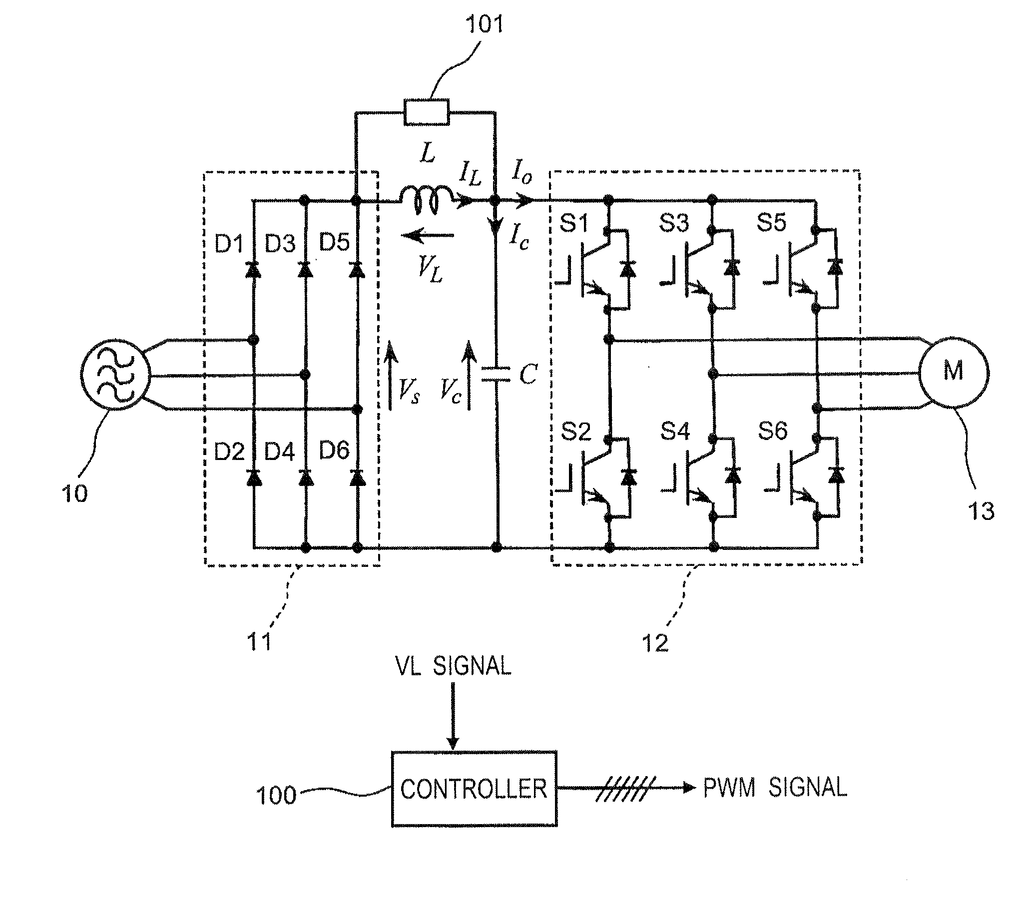
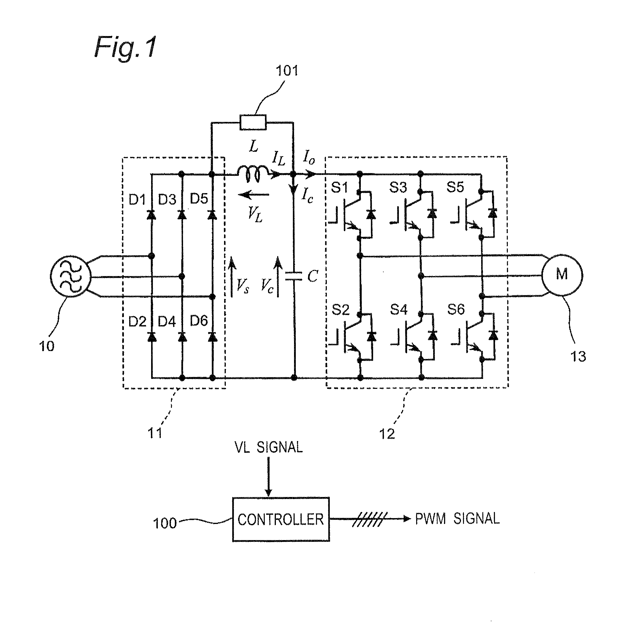
[0106]FIG. 1 shows a constructional view of a power converter according to a first embodiment of the invention. This power converter, as shown in FIG. 1, includes a diode bridge 11 as an example of a rectifier section composed of six diodes D1-D6 composing a three-phase diode bridge circuit, and an inverter section 12 composed of six switching elements S1-S6 composing a three-phase bridge circuit. The power converter also includes a reactor L as an example of an inductance element connected between a positive-pole side output end of the diode bridge 11 and a positive-pole side input end of the inverter section 12, and a capacitor C as an example of a capacitance element connected between input ends of the inverter section 12. The reactor L and the capacitor C constitute an LC filter. The power converter further includes a voltage detector 101 for detecting a voltage across the reactor L, and a controller 100 for outputting a PWM signal to each of the switching elements S1-S6 of the ...

second embodiment

[0180]Next, a power converter according to a second embodiment, which is enabled to improve the stability of the control system of the power converter according to the first embodiment, will be described below.

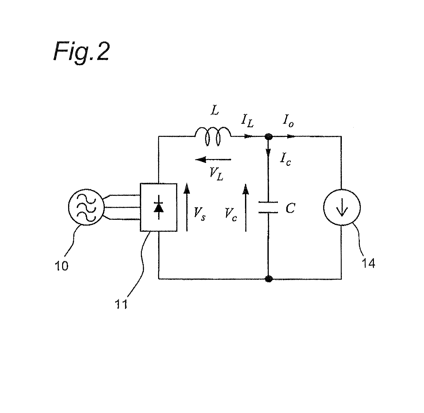
[0181]The power converter of the second embodiment of the invention is similar in construction to the power converter of the first embodiment shown in FIG. 1 except the operation of the controller 100, and therefore FIGS. 1 and 2 are used for reference.

[0182]FIGS. 20(A), 20(B) and 20(C) show block diagrams of the power converter of the second embodiment.

[0183]FIG. 20(A)-20(C), which are block diagrams resulting from determining characteristics of the resonance suppression system with the voltage VL across the reactor L used for resonance suppression, show transfer characteristics of the voltage Vc across the capacitor C (i.e., input voltage of the inverter section 12) versus the DC voltage Vs outputted from the diode bridge 11.

[0184]It can be seen that executing equivalent tra...


PUM


Abstract

A power converter includes a rectifier section, an inverter section, a capacitance element connected between inverter section input ends, an inductance element forming part of an LC filter with the capacitance element, a voltage detector detecting an inductance element voltage, and a controller controlling the inverter section based on the detected voltage. The LC filter has a resonance frequency set such that ripple current components contained in DC current outputted from the rectifier section passes through, and current components of a frequency equal to a carrier frequency of the inverter section are dampened. The controller controls the inverter section so that a transfer characteristic of input voltage of the inverter section versus the DC voltage from the rectifier section becomes a damping characteristic given by a phase lead element and a second-order lag element connected in series, and a damping coefficient of the transfer characteristic is set larger than 1.

Description

TECHNICAL FIELD[0001]The present invention relates to a power converter.BACKGROUND ART[0002]As a typical main circuit construction for power converters, there has generally been used an indirect-type AC power converter in which commercial AC voltage is converted into DC voltage via a rectifier circuit and a smoothing circuit and then AC power is obtained by a voltage-type converter. Meanwhile, as a method for obtaining an AC output directly from AC voltage, there is known a three-phase capacitorless inverter which eliminates the need for large-scale capacitors or reactors for use of smoothing voltage pulsations due to commercial frequency so that downsizing of power converters becomes implementable.[0003]As a conventional first power converter, there is provided a direct-type AC power conversion circuit in which sextuple-harmonic currents toward the power supply side are suppressed (see, e.g., JP 4488122 B (PATENT LITERATURE (PTL) 1)).[0004]As a conventional second power converter, ...

Claims


Application Information

Patent Timeline
Patent Type & Authority Applications(United States)
IPC IPC(8): H02M5/458
CPCH02M5/458H02M1/15H02M7/4826H02M7/53875
Inventor SAKAKIBARA, KENICHIOHTA, KEISUKE
Owner DAIKIN IND LTD
Why Eureka
Try Eureka