
Dense material including carbon nanohorns and use thereof

Inactive Publication Date: 2014-11-06
ENVIRONMENT ENERGY NANOTECH RES INST COLTD
View PDF3 Cites 10 Cited by
  • Summary
  • Abstract
  • Description
  • Claims
  • Application Information

AI Technical Summary

Benefits of technology

This patent aims to address the problems faced by carbon nanomaterials such as shape anisotropy, hydrophobicity, prone to aggregate, and lack of binding property. The goal is to provide a dense material that includes carbon nanomaterial and the use thereof. The technical effects of the patent is to overcome the issues associated with carbon nanomaterials and create a reliable and useful material for various applications.

Problems solved by technology

When providing a shape to the carbon nanomaterial, basic problems such as moldability and binding properties arise, while when forming a composite, other basic problems such as miscibility with another material, moldability, and strength arise.

Method used


Image

  • Dense material including carbon nanohorns and use thereof
  • Dense material including carbon nanohorns and use thereof
  • Dense material including carbon nanohorns and use thereof

Examples


first embodiment

[0183]The present teaching is described in detail below with reference to the embodiments. The present teaching, however, is not limited by the following embodiments. In the embodiments, production of carbon nanohorn by the production method of the present teaching is described.

second embodiment

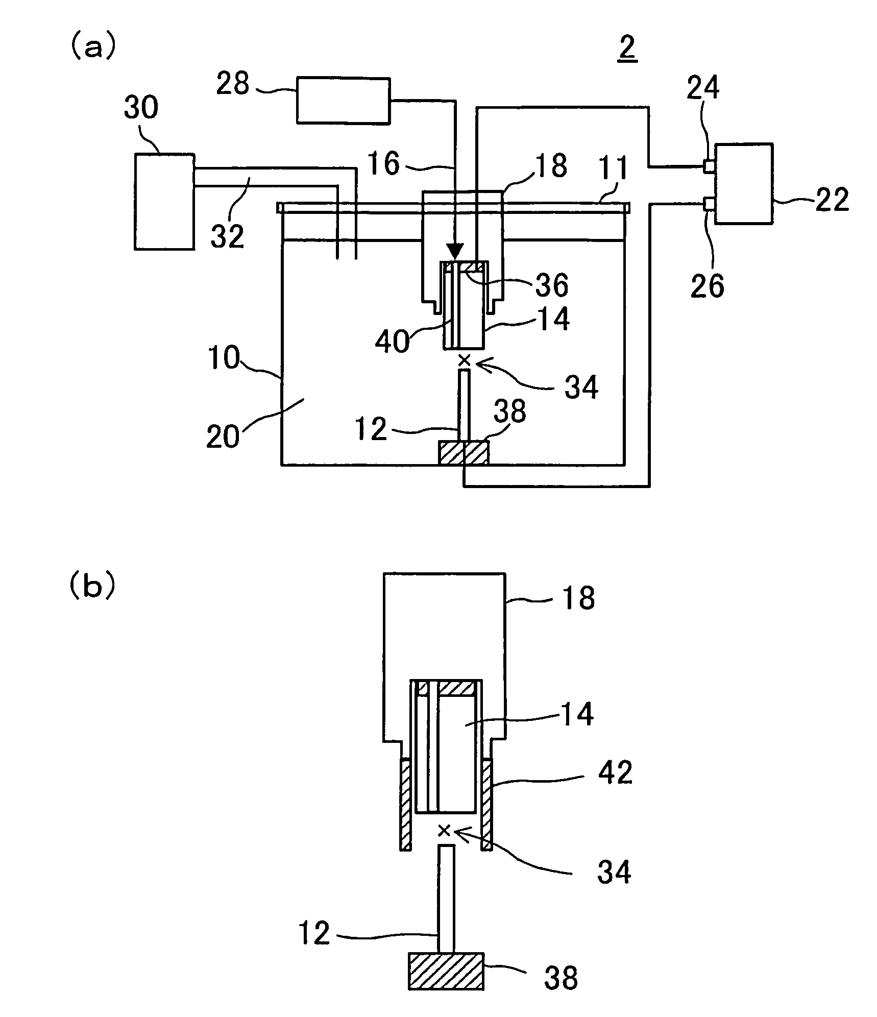
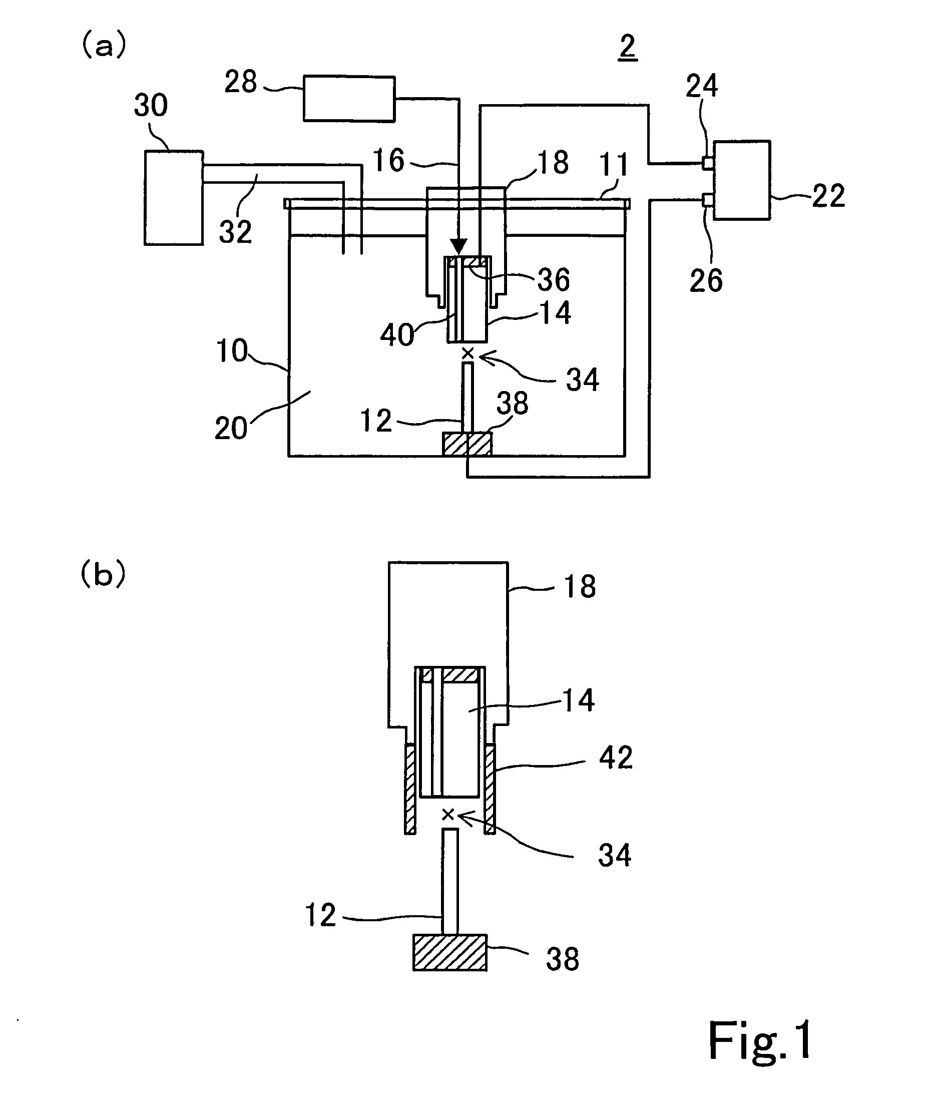
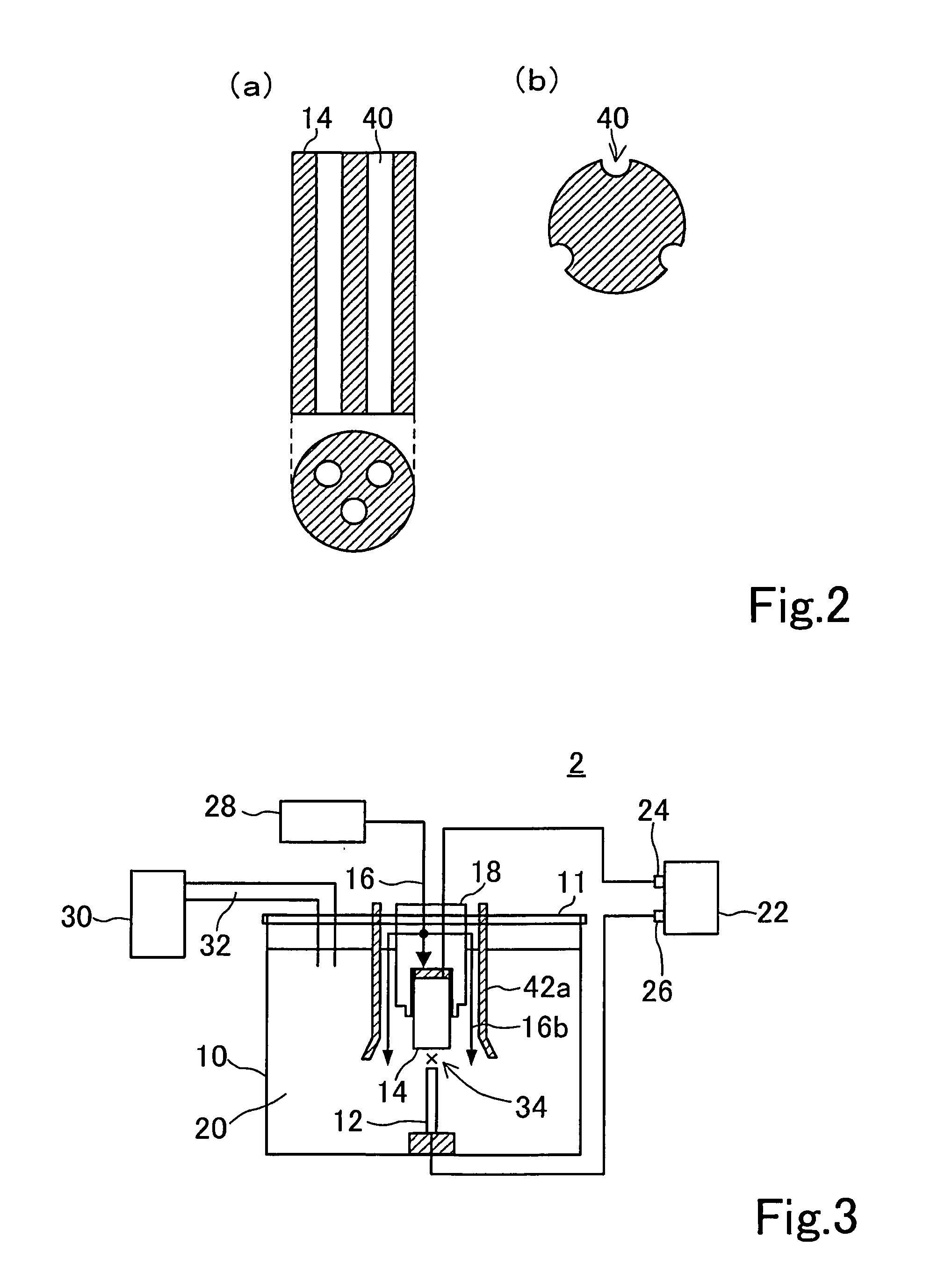
[0184]The present embodiment is described as a favorable example of a device of FIGS. 1A and 1B. The graphite positive electrode and the negative electrode are disposed in the fluid bath with a water depth of about 30 cm so that the electrodes face each other in the vertical direction in relation to force of gravity at a distance of 1 mm from each other. The graphite positive electrode has a cylindrical shape with a diameter of 3 mm and a length of 100 mm and is obtained using 1.5 g of carbon rods with a carbon purity of 99.999%. The fluid bath is filled with 20 L of aqueous solution, and the fluid bath is then sealed with a lid. A DC voltage of 20 V, 60 A is applied to the graphite positive electrode and the negative electrode. Carbon particles are then synthesized by supplying nitrogen gas at at a set value (20 L / min to 25 L / min) to the introducing path of the negative electrode. At that time, a gap between the graphite anode and the cathode is adjusted by automatic control of a s...

third embodiment

[0187]In the present embodiment, a carbon nanomaterial was produced using a graphite anode in a size that is different from the first embodiment. The description of the same members and the same operations were omitted. In the present embodiment, as the graphite anode, a carbon rod having a diameter of 6.8 mm, a length of 100 mm, a cylindrical shape, and a carbon purity of 99.999% was used. As the cathode, a carbon rod, which has a diameter of 12.3 mm and in which a nitrogen gas introduction path was formed, was used. The graphite anode and the cathode was placed in a fluid bath so as to face each other at a distance of 1 mm, and the fluid bath was filled with purified water, and thereafter, a direct current at 140 A was applied under introduction of nitrogen gas (20 to 25 litters / minute) to generate a carbon nanomaterial. The generated carbon nanomaterial was separated by filtration. Thus, 3 to 4 times as much carbon nanohorns as that in the first embodiment were obtained.

[0188]As ...


PUM

PropertyMeasurementUnit
Temperatureaaaaaaaaaa
Lengthaaaaaaaaaa
Fractionaaaaaaaaaa

Abstract

The purpose of showing the present description is to provide a dense material containing carbon nanohorns. For this purpose, the present description shows the dense material containing carbon nanohorns and having a predetermined three-dimensional shape.

Description

TECHNICAL FIELD[0001]The present description relates to a dense material containing carbon nanohorns and the use thereof.BACKGROUND ART[0002]Carbon substances having nanometer-scale microstructures, such as single-walled or multi-walled carbon nanotubes, carbon nanohorns, fullerenes, and nanocapsules, have recently attracted much attention. Such carbon substances are expected to find applications as nanostructured graphite substances for new electronic materials, catalysts, and optical materials. In particular, carbon nanohorns have attracted attention as substances that are the closest to practical use in electrode materials or gas-adsorbing materials of fuel cells.[0003]On the other hand, in order to develop a wider range of application of such carbon nanomaterial, it is necessary to, for example, mold powdery carbon nanomaterial into a predetermined shape or form a composite of carbon nanomaterial together with another material. When providing a shape to the carbon nanomaterial, ...

Claims


Application Information

Patent Timeline
IPC IPC(8): H05K9/00C01B31/02B29C35/00
CPCH05K9/0083B29C35/00C01B31/0293B29K2105/251B82Y25/00Y10S977/734Y10S977/842B82Y40/00Y10S264/00B82Y30/00H01M4/96C04B35/117C04B35/645C04B2235/404C04B2235/422C04B2235/5276C04B2235/5409C04B2235/5445C04B2235/5454C04B2235/5481C04B2235/666C04B2235/77C04B2235/95H01M8/0234H01M4/625C04B35/528C04B2235/6562C04B2235/6567C04B2235/72C04B2235/724C01B32/18Y10T428/25Y10T428/249953Y02P70/50Y02E60/50Y02E60/10C04B35/80
Inventor GOINO, TADASHIKITAMURA, TSUZUKI
Owner ENVIRONMENT ENERGY NANOTECH RES INST COLTD
Learn More