Hydraulic Machinery

a technology of hydraulic pump and hydraulic pump, which is applied in the direction of rotary clutches, electrical control, fluid couplings, etc., can solve the problems of insufficient speed and inability to solve, and achieve the effects of improving the discharge flow rate of hydraulic pumps, improving operability, and reducing fuel consumption

Inactive Publication Date: 2014-11-13
CATEPILLAR SARL
View PDF4 Cites 3 Cited by
  • Summary
  • Abstract
  • Description
  • Claims
  • Application Information

AI Technical Summary

Benefits of technology

[0007]With the invention of claim 1, even in the case where the engine rotation speed is set to be low during normal operation to achieve lower fuel consumption, the engine rotation speed increases when the engine rotation speed increasing control is performed, and thus the discharge flow rate of the hydraulic pump can be increased. This can prevent insufficient speed due to an insufficient supply flow rate to the hydraulic actuator in the case where an operation requiring high speed at a light load is performed, whereby excellent operability is guaranteed and an attempt to improve work efficiency is largely facilitated.

Problems solved by technology

As a result, the problem of the insufficient speed, when the hydraulic actuator is to be operated at a high speed in the light load state, cannot be solved.

Method used


Image

  • Hydraulic Machinery
  • Hydraulic Machinery
  • Hydraulic Machinery

Examples


Embodiment Construction

[0010]An embodiment of the present invention is described below by referring to the drawings.

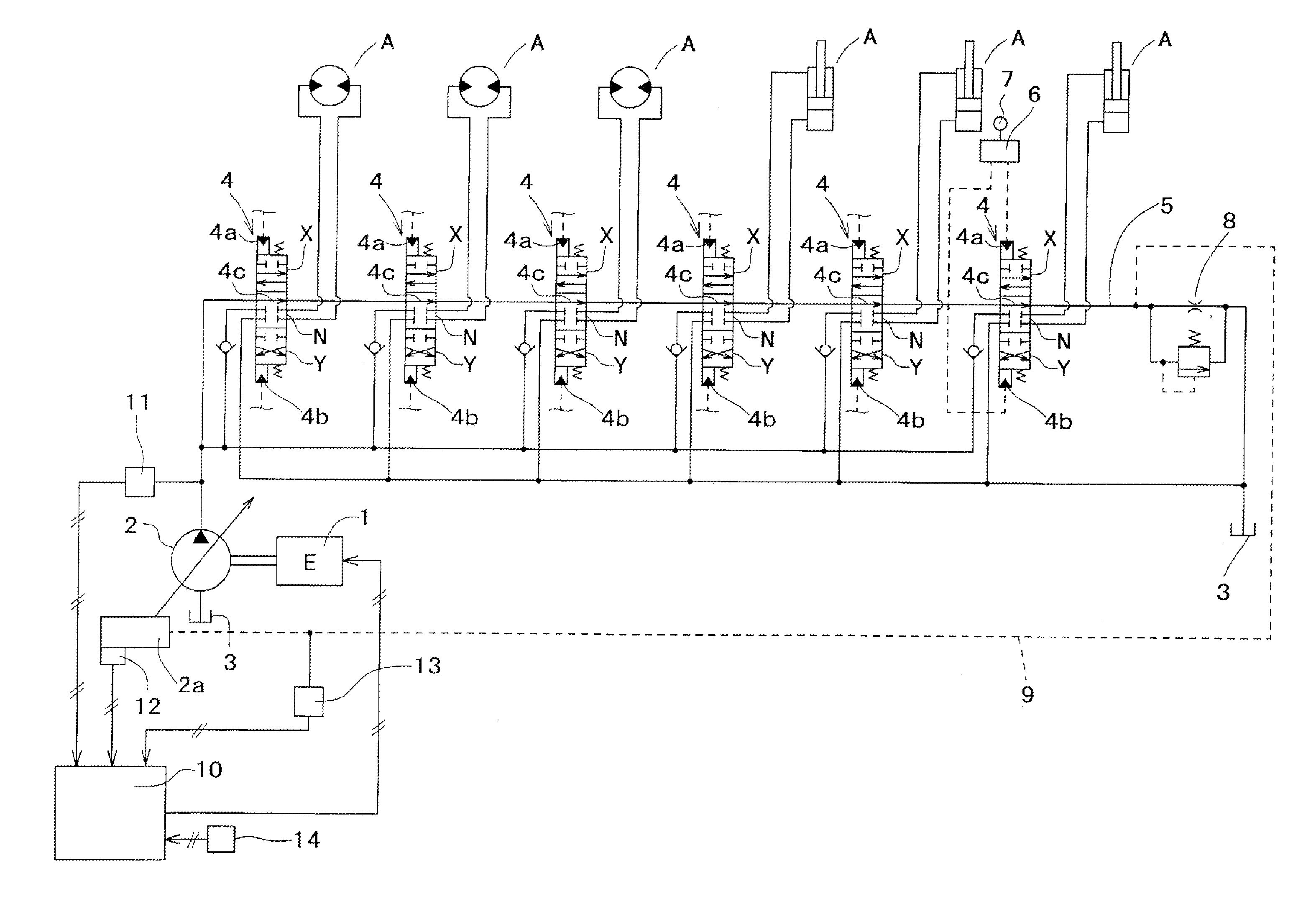
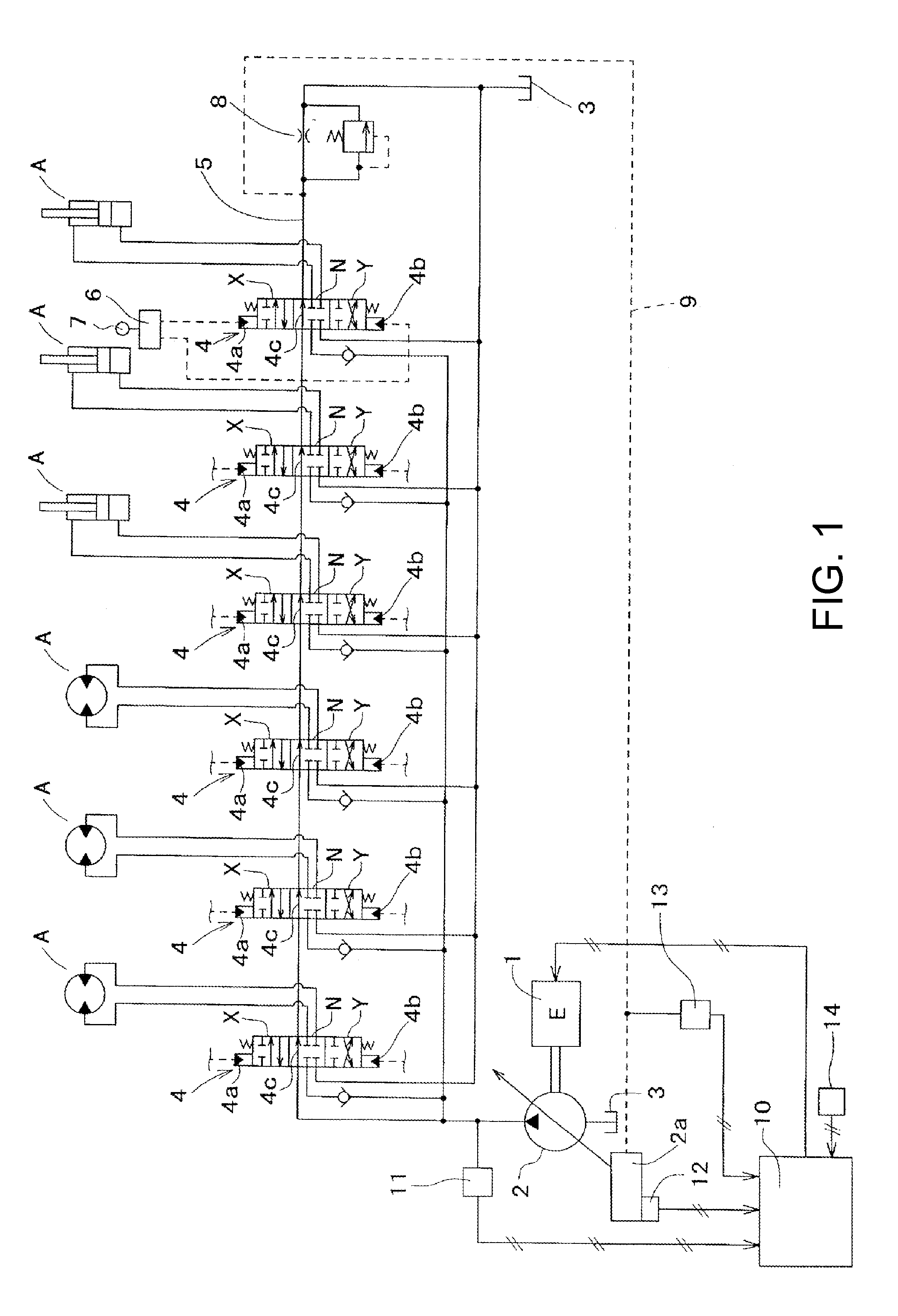
[0011]A hydraulic pressure control circuit provided to a hydraulic shovel, as an example of a hydraulic work machine, is illustrated in FIG. 1, in which 1 denotes an engine, 2 denotes a variable capacity hydraulic pump driven by the engine 1, 2a denotes capacity varying means of the hydraulic pump 2, 3 denotes an oil tank, and A denotes hydraulic actuators that operate using the hydraulic pump 2 as a hydraulic pressure supply source. In this embodiment, the hydraulic shovel includes, as the hydraulic actuators A, left and right drive motors, a swing motor, a boom cylinder, an arm cylinder, and a bucket cylinder. In this embodiment, an axial piston pump, in which a capacity changes in accordance with a inclination angle of a swash plate, is used as the hydraulic pump 2.

[0012]Furthermore, 4 denotes control valves that perform oil supply / discharge control for the respective hydraulic actuators ...


PUM


Abstract

The invention addresses the problem of avoiding insufficient flow being supplied to the hydraulic actuator and speed becoming insufficient during light loads in hydraulic machinery such as hydraulic shovels when the engine rotation speed is set low during normal work. The solution is to increase the discharge flow of the hydraulic pump (2) by increasing the rotation speed of the engine (1) above the target rotation speed set by the engine rotation speed-setting means (14) when the hydraulic pump (2) discharge pressure is at the light load pump discharge pressure, the hydraulic pump (2) inclination angle is at the maximum inclination angle, and the negative control signal pressure is at the signal pressure when the hydraulic actuator-operating means (7) is at full operation.

Description

TECHNICAL FIELD[0001]The present invention relates to the technical field of a hydraulic work machine such as a hydraulic shovel.BACKGROUND ART[0002]Generally, hydraulic work machines, such as hydraulic shovels, are configured to drive a hydraulic pump by an engine to operate various hydraulic actuators (a hydraulic motor and a hydraulic cylinder) that use the hydraulic pump as a hydraulic pressure supply source, and thus perform various operations such as traveling and excavation. In recent years, improvements in fuel efficiency and reductions of exhaust gases in these hydraulic work machines have been in progress. One studied method of achieving the objects is setting the engine rotation speed to be low during normal operation. However, when the engine rotation speed is thus set to be low, the rotation speed of the hydraulic pump, driven by the engine, is also lowered. Thus, the maximum flow rate that can be supplied from the hydraulic pump to the hydraulic actuator is reduced. As...

Claims


Application Information

Patent Timeline
Patent Type & Authority Applications(United States)
IPC IPC(8): E02F9/22
CPCE02F9/2246E02F9/2296E02F9/2285F02D29/04F02D41/0205F02D41/021F15B1/083F15B1/24
Inventor HATA, YOSHIHIKOTADA, SHOGO
Owner CATEPILLAR SARL
Why Eureka
Try Eureka