Electron beam plasma source with reduced metal contamination

Inactive Publication Date: 2014-11-20
APPLIED MATERIALS INC
View PDF5 Cites 3 Cited by
  • Summary
  • Abstract
  • Description
  • Claims
  • Application Information

AI Technical Summary

Benefits of technology

[0011]In one embodiment, the strength of the magnetic field and the voltage of the acceleration voltage source

Problems solved by technology

This leads to metal contamination of the processing cham

Method used


Image

  • Electron beam plasma source with reduced metal contamination
  • Electron beam plasma source with reduced metal contamination
  • Electron beam plasma source with reduced metal contamination

Examples


Embodiment Construction

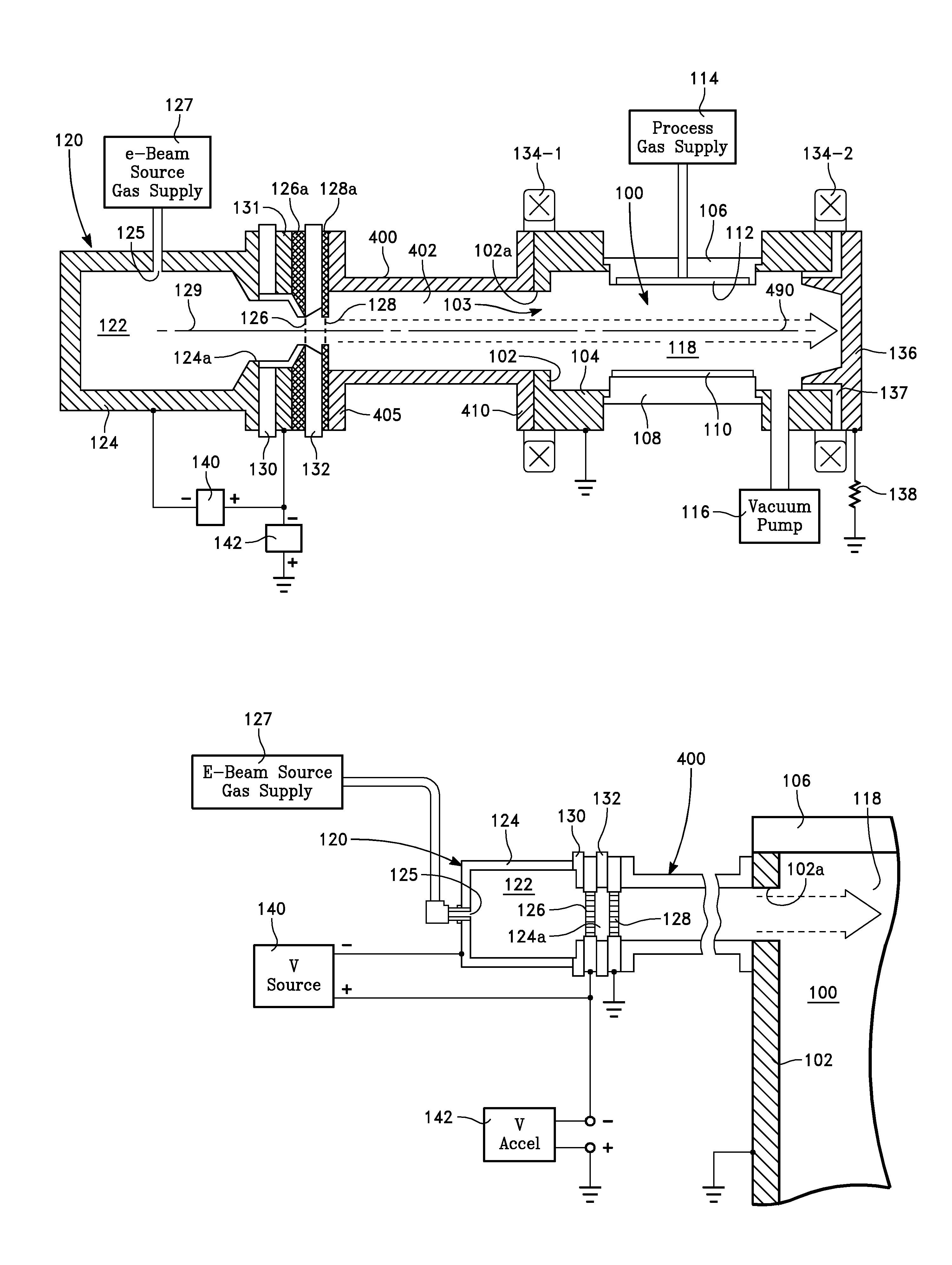
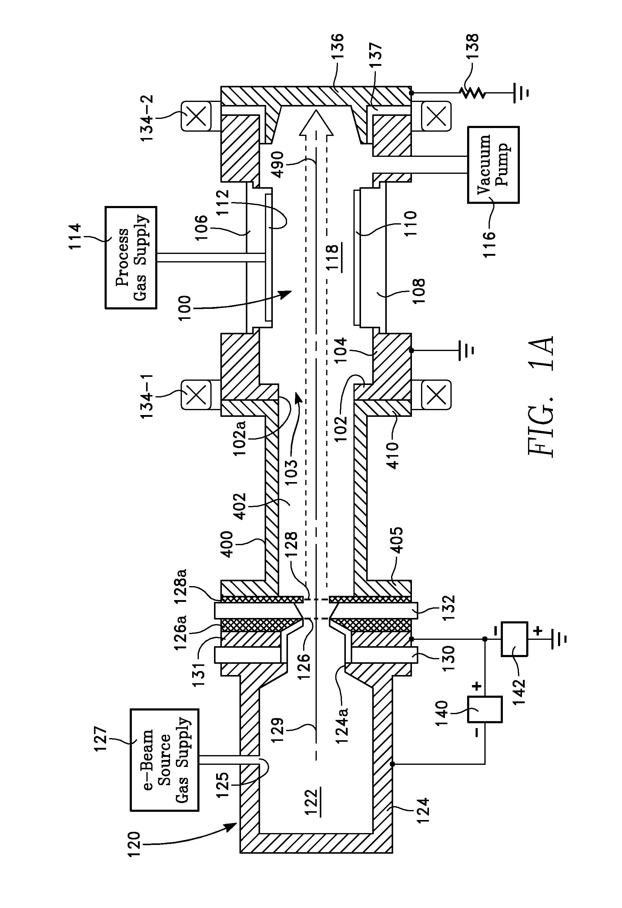
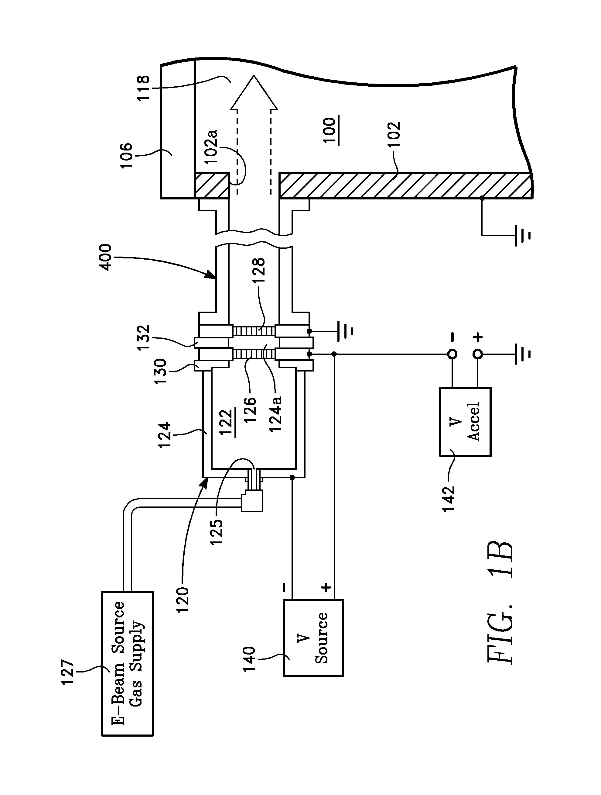
[0026]Referring toFIGS. 1A-1C, a plasma reactor has an electron beam as a plasma source. The reactor includes a processing chamber 100 enclosed by a cylindrical side wall 102, a floor 104 and a ceiling 106. A workpiece support pedestal 108 supports a workpiece 110, such as a semiconductor wafer, the pedestal 108 being movable in the axial (e.g., vertical) direction. A gas distribution plate 112 is integrated with or mounted on the ceiling 106, and receives process gas from a process gas supply 114. A vacuum pump 116 evacuates the chamber through a passage in the floor 104. A processing region 118 is defined between the workpiece 110 and the gas distribution plate 112. Within the processing region 118, the process gas is ionized to produce a plasma for processing of the workpiece 110.

[0027]The plasma is generated in the processing region 118 by an electron beam from an electron beam source 120. The electron beam source 120 includes a plasma generation chamber 122 spaced from the proc...


PUM

PropertyMeasurementUnit
Magnetic fieldaaaaaaaaaa
Electric potential / voltageaaaaaaaaaa
Strengthaaaaaaaaaa

Abstract

In a plasma reactor for processing a workpiece, an electron beam is employed as the plasma source, and sputtered metal atoms are removed from the electron beam to reduce contamination.

Description


Claims


Application Information

Patent Timeline
Owner APPLIED MATERIALS INC
Why Eureka
Try Eureka