Method for enhanced oil recovery by in situ carbon dioxide generation

a carbon dioxide and in situ technology, applied in the field of enhanced oil recovery, can solve the problems of reducing sweep efficiency, affecting oil recovery, and affecting oil recovery, etc., and achieve the effect of maximizing oil extraction and enhancing oil recovery

Inactive Publication Date: 2014-11-20
KING FAHD UNIVERSITY OF PETROLEUM AND MINERALS
View PDF8 Cites 34 Cited by
  • Summary
  • Abstract
  • Description
  • Claims
  • Application Information

AI Technical Summary

Problems solved by technology

However, carbon dioxide flooding processes frequently experience viscous fingering and gravity override problems because of the very low density and viscosity of the carbon dioxide when compared to those of crude oil.
As a result, sweep efficiency is decreased, compared with more dense and / or viscous fluids, and significant amounts of oil are left behind.
Surfactants have been used as foaming agents, but surfactants suffer from thermal stability problems, typically being unstable at temperatures exceeding 100° C.
Overall, oil recovery by this process was very low, with only 43% residual oil recovery after surfactant / polymer injection.
However, HCl is very corrosive.
Thus, costly corrosion inhibitors need to be added.
A further problem is that the HCl cannot be used in carbonate reservoirs due to the reaction between the HCl with the carbonate.

Method used


Image

  • Method for enhanced oil recovery by in situ carbon dioxide generation

Examples


Embodiment Construction

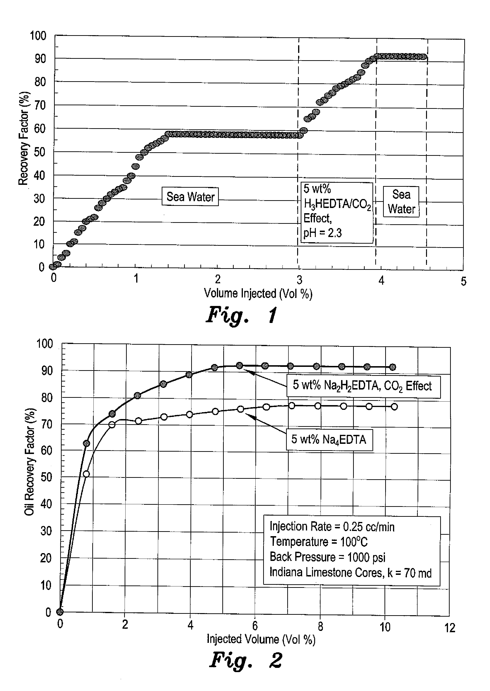
[0016]The method for enhanced oil recovery by in situ carbon dioxide generation utilizes a chelating fluid injected into an oil reservoir through a fluid injection system. The chelating fluid is a low pH solution of a polyamino carboxylic acid chelating agent. The polyamino carboxylic acid chelating agent may have a concentration of about 5 wt %. The polyamino carboxylic acid chelating agent is preferably either an aqueous solution of H2Na2-ethylenediaminetetraacetic acid (pH 4.5), H3-hydroxyethyl ethylenediamine triacetic acid (pH 2.5), or an aqueous solution of H2NaHEDTA (pH 4). The chelating fluid may be injected at a rate of approximately 0.25 mL / min. The injection of the chelating fluid may be preceded by flooding the core with seawater, and is followed by injection of either seawater, a high pH chelating agent, or low salinity water to ensure maximal extraction of oil from the reservoir. The method is particularly for use in formations where the core of the reservoir has a car...


PUM


Abstract

The method for enhanced oil recovery by in situ carbon dioxide generation utilizes a chelating fluid injected into an oil reservoir through a fluid injection system. The chelating fluid is a low pH solution of a polyamino carboxylic acid chelating agent. The polyamino carboxylic acid chelating agent may have a concentration of about 5 wt %. The polyamino carboxylic acid chelating agent is preferably either an aqueous solution of H2Na2-ethylenediaminetetraacetic acid (pH 4.5), H3-hydroxyethyl ethylenediamine triacetic acid (pH 2.5), or an aqueous solution of H2NaHEDTA (pH 4). The injection of the chelating fluid may be preceded by flooding the core with seawater, and is followed by injection of either to seawater, a high pH chelating agent, or low salinity water to ensure maximal extraction of oil from the reservoir. The method is particularly for use in formations where the core of the reservoir has a carbonate rock matrix.

Description

BACKGROUND OF THE INVENTION[0001]1. Field of the Invention[0002]The present invention relates to oil recovery operations, and particularly to a method for enhanced oil recovery by in situ carbon dioxide generation.[0003]2. Description of the Related Art[0004]Enhanced oil recovery (EOR) is a technique for increasing the amount of crude oil that can be extracted from an oil field. Gas injection, or miscible flooding, is presently the most commonly used approach in enhanced oil recovery. Miscible flooding is a general term for injection processes that introduce miscible gases into the reservoir. A miscible displacement process maintains reservoir pressure and improves oil displacement because the interfacial tension between oil and water is reduced by removal of the interface between the two interacting fluids. This allows for total displacement efficiency. Gases used for miscible flooding include carbon dioxide, natural gas, and nitrogen.[0005]The fluid most commonly used for miscible...

Claims


Application Information

Patent Timeline
Patent Type & Authority Applications(United States)
IPC IPC(8): E21B43/20
CPCE21B43/20C09K8/58C09K8/594
Inventor MAHMOUD, MOHAMED AHMED NASR EL-DINSULTAN, ABDULLAH SAADABDELGAWAD, KHALED ZIDAN
Owner KING FAHD UNIVERSITY OF PETROLEUM AND MINERALS
Why Eureka
Try Eureka