Ultraviolet diode and atomic mass analysis ionization source collecting device using ultraviolet diode and an mcp

a technology of atomic mass analysis and collecting device, which is applied in the field of electron guns, can solve the problems of difficult control of electron emission in mass analyzers, slow reaction to electron emission caused by rise to high temperature, and rapid consumption of battery power in portable mass analyzers, etc., and achieves the effect of reducing size, weight and battery power consumption, and focusing with relative eas

Active Publication Date: 2014-11-20
KOREA BASIC SCI INST
View PDF4 Cites 11 Cited by
  • Summary
  • Abstract
  • Description
  • Claims
  • Application Information

AI Technical Summary

Benefits of technology

[0007]As described above, the device for acquiring an ion source of a mass analyzer using an ultraviolet (UV) diode and a micro-channel plate (MCP) can produce the electron beam for ionizing the gaseous sample molecules at a low temperature without using a high temperature and a high current, r

Problems solved by technology

However, due to high power consumption, battery power is rapidly consumed in a portable mass analyzer, and a reaction to electron emission caused by a rise to a high temperature is slow.
A

Method used


Image

  • Ultraviolet diode and atomic mass analysis ionization source collecting device using ultraviolet diode and an mcp
  • Ultraviolet diode and atomic mass analysis ionization source collecting device using ultraviolet diode and an mcp
  • Ultraviolet diode and atomic mass analysis ionization source collecting device using ultraviolet diode and an mcp

Examples


Embodiment Construction

[0010]Hereinafter, exemplary embodiments of the present invention will be described in detail below with reference to the attached drawings. While the present invention is shown and described in connection with exemplary embodiments thereof, it will be apparent to those skilled in the art that various modifications can be made without departing from the spirit and scope of the invention.

[0011]A device for acquiring an ion source of a mass analyzer using an ultraviolet (UV) diode and a micro-channel plate (MCP) in accordance with an embodiment of the present invention will be described below in detail with reference to the attached drawings.

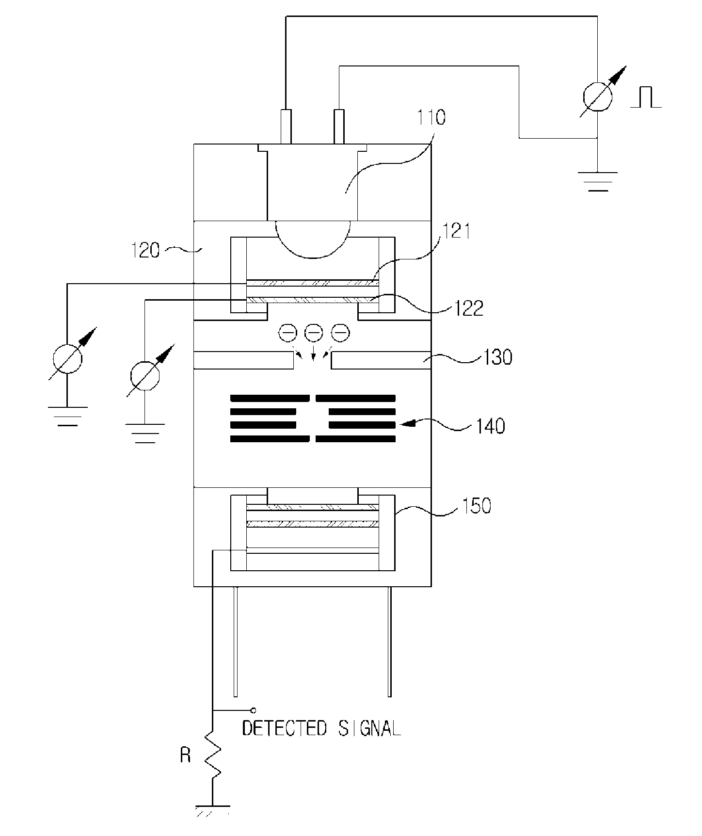
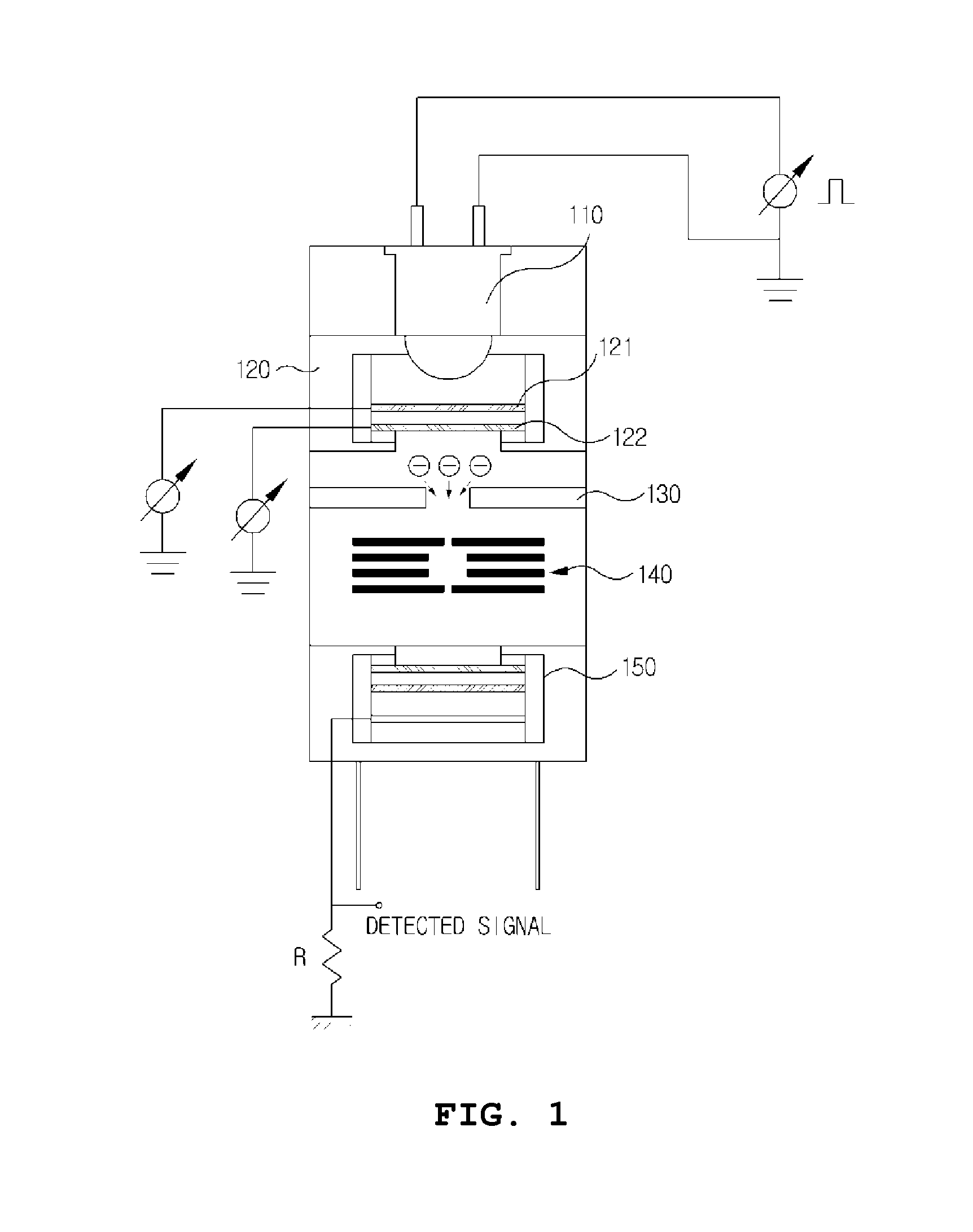
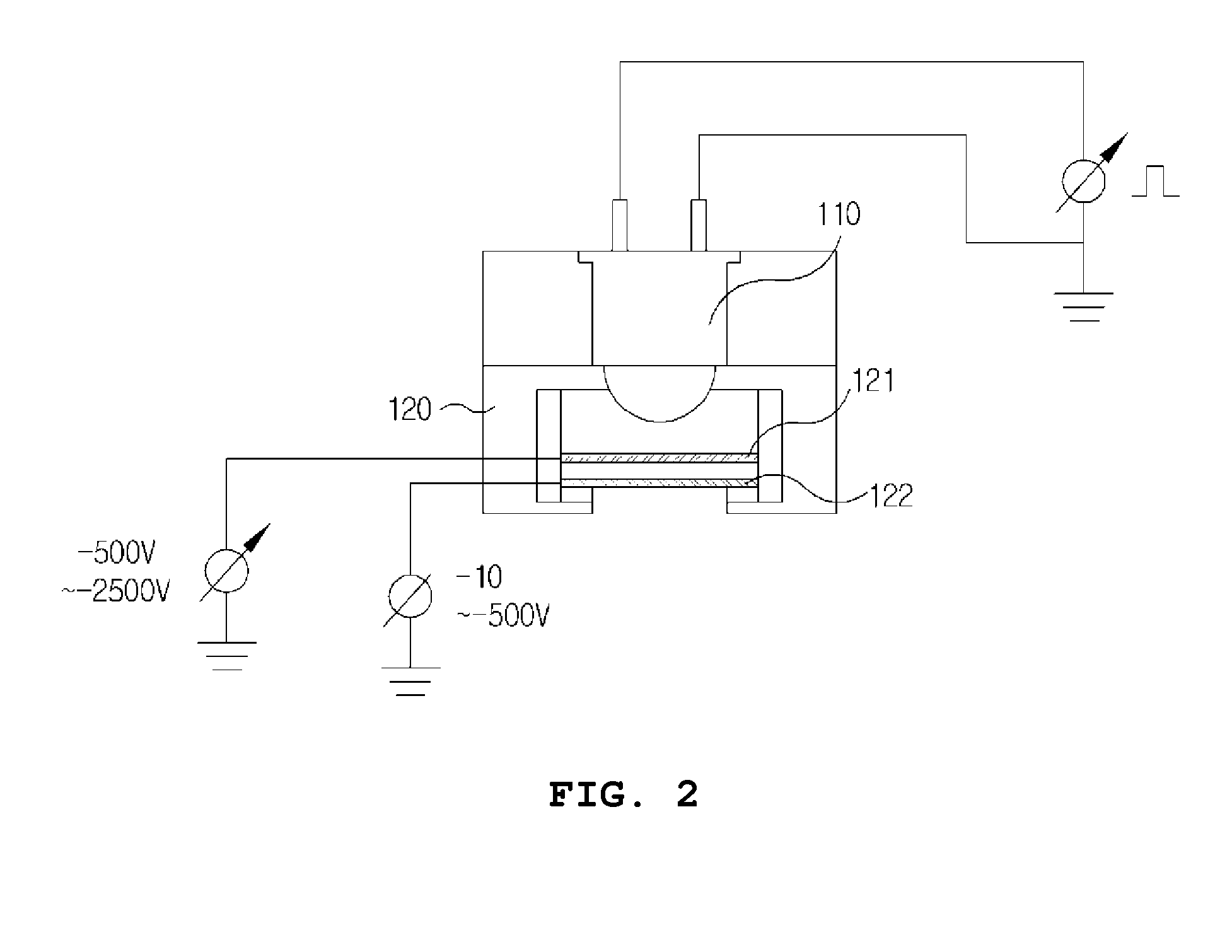
[0012]FIG. 1 shows a configuration of a device for acquiring an ion source of a mass analyzer using a UV diode and an MCP in accordance with an embodiment of the present invention. The device includes a UV diode 110 emitting UV using supplied power, an MCP electron multiplier plate 120 causing the UV photons from the UV diode 110 to induce initial...


PUM

PropertyMeasurementUnit
Pressureaaaaaaaaaa
Electric potential / voltageaaaaaaaaaa

Abstract

The present invention relates to an ultraviolet diode and an atomic mass analysis ionization source collecting device using an MCP. In the manufacturing of a portable atomic mass analyzer, an object of the present invention is to use an MCP electron multiplier plate, whereby ultraviolet photons emitted from an ultraviolet diode are irradiated on a front surface plate of the MCP electron multiplier plate to induce primary electrons, an amplified electron beam is collected from the electrons, and an electron beam is generated at a low temperature and low power and having a discharge time that is accurately controlled. The atomic mass analysis ionization source collecting device using an ultraviolet diode and an MCP according to the present invention comprises: an ultraviolet diode emitting ultraviolet rays by means of supplied power; an MCP electron multiplier plate inducing and amplifying primary electron discharge from ultraviolet photons from the ultraviolet diode, and collecting a large amount of electron beams from an MCP reverse surface plate; an electron condenser lens condensing the electron beam amplified through the MCP electron multiplier plate; an ion trap atomic mass separator ionizing gas sample molecules by means of an electron beam injected through the electron condenser lens; and an ion detector performing detection of ions separated from the ion trap atomic mass separator, by means of an atomic mass spectrum.

Description

TECHNICAL FIELD[0001]The present invention relates to an electron gun for ionizing gaseous molecules in a mass analyzer and, more particularly, to a device for acquiring an ion source of a mass analyzer using an ultraviolet (UV) diode and a micro-channel plate (MCP), in which cold electrons are produced at room temperature using the UV diode and an MCP electron multiplier plate, and are applied to the mass analyzer, without using a thermionic emission method based on a high temperature and a high current.BACKGROUND ART[0002]In general, to separate molecular ions to analyze components according to the masses of the ions in a mass analyzer, first, a process of ionizing gaseous molecules is required.[0003]A method of bombarding the gaseous molecules with an electron beam to produce the molecular ions is most frequently used. To produce the electron beam, a device for heating a filament at a high temperature to induce thermionic emission is most widely used.[0004]The filament can be hea...

Claims


Application Information

Patent Timeline
IPC IPC(8): H01J49/16
CPCH01J49/161H01J49/0022H01J49/08H01J49/424Y10T29/49826H01J49/26H01J49/4225G01N27/623H01J2225/76
Inventor KIM, SEUNG YONGYANG, MOKIM, HYUN SIK
Owner KOREA BASIC SCI INST
Why Eureka
Try Eureka