Driving device

Active Publication Date: 2014-11-20
DENSO CORP
View PDF4 Cites 38 Cited by
  • Summary
  • Abstract
  • Description
  • Claims
  • Application Information

AI Technical Summary

Benefits of technology

[0014]According to the above structure, a contacting area between the casing and the frame member is reduced. As a result, the noise generated by the vibration or the like can be reduced, when compared with a case in which the casing and the frame member are brought into contact with each other at its whole surface area. In addition, since it is possible to surely obtain sufficient surface pressure at the contacting surface area, the mechanical strength can be increased in the axial direction.
[0015]Furthermore, since the frame member, to which the control unit is fixed, and the casing are made of the independent parts from each other, it is possible to select appropriate material for each of the parts. For example, when the casin

Problems solved by technology

In a case that the cover member or another member fixed to the cover member is brought into contact with the motor housing at its whole surface area for the purpose of increasing the mechanical strength, it is

Method used


Image

  • Driving device
  • Driving device
  • Driving device

Examples


first embodiment

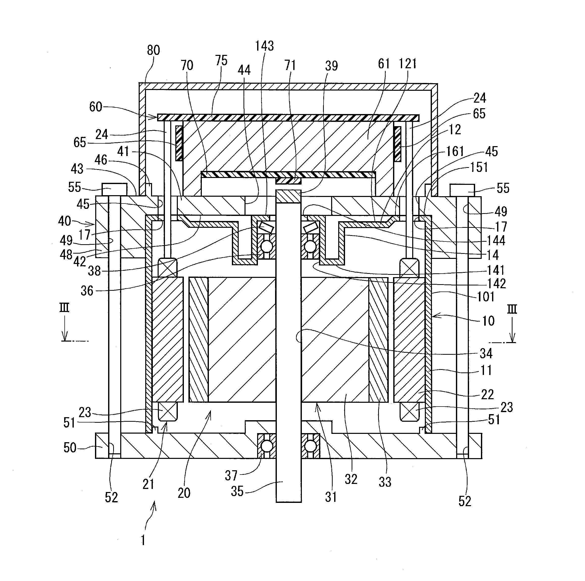
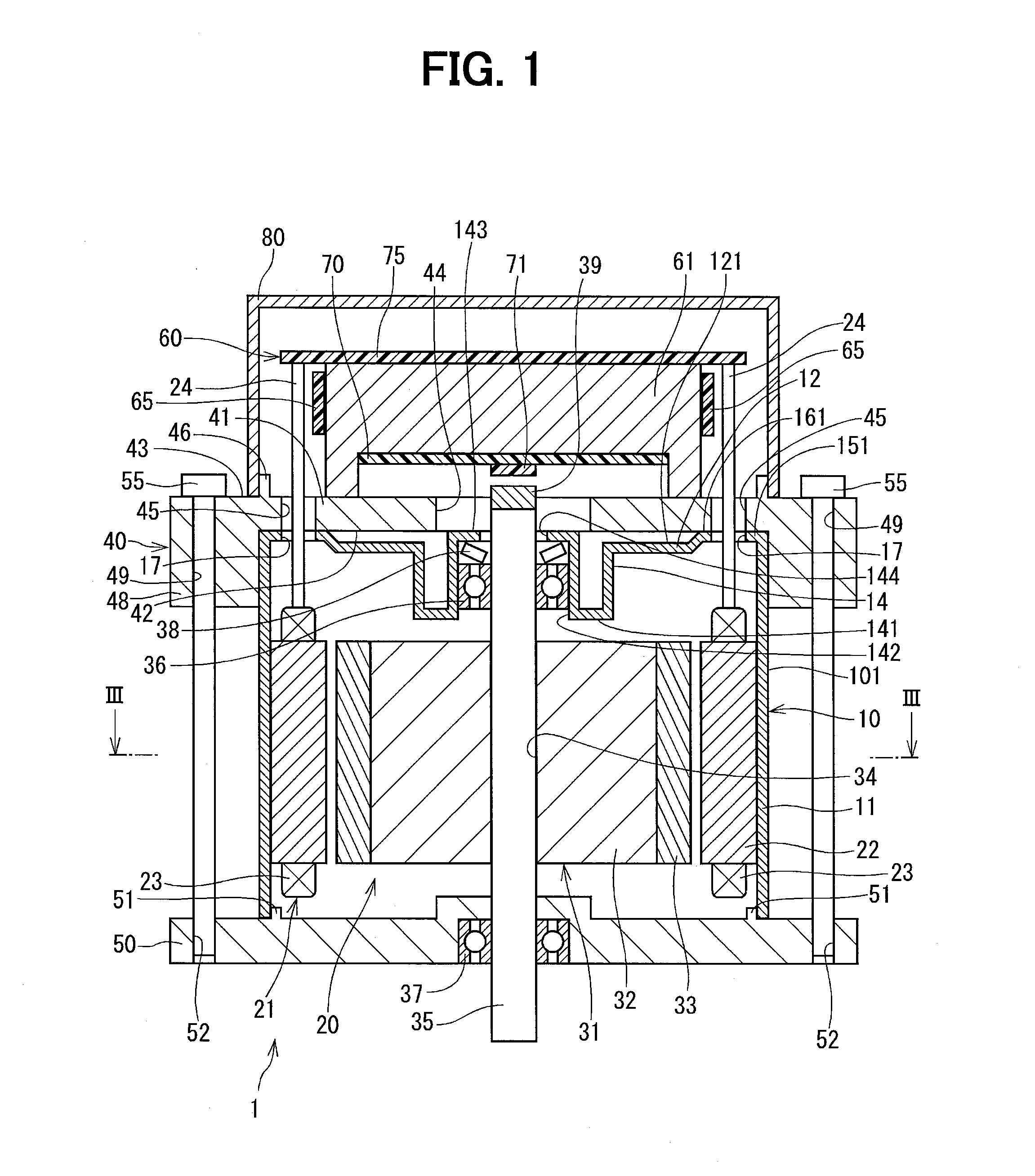
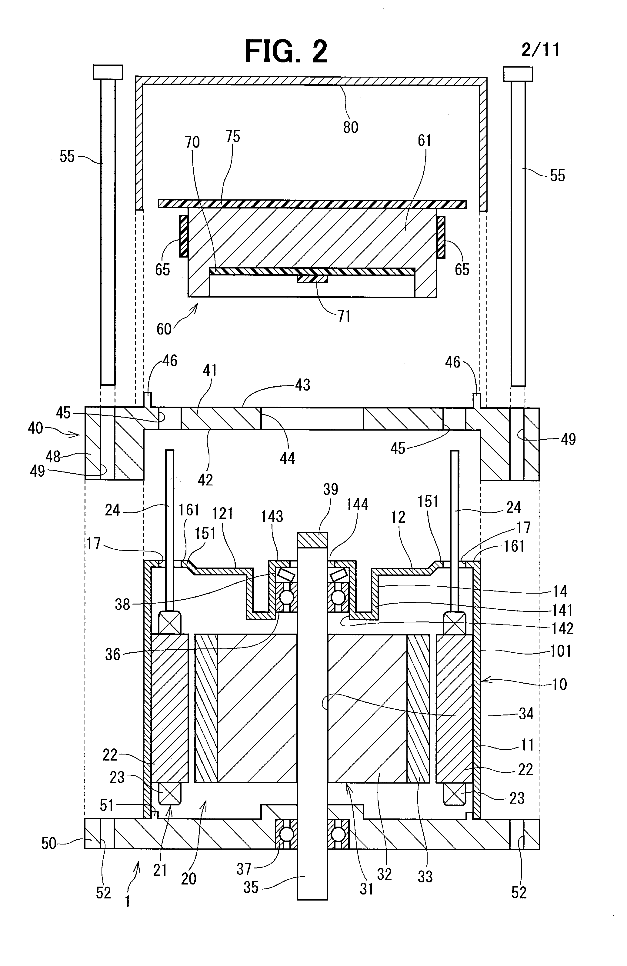
[0030]A motor driving device 1 of a first embodiment of the present disclosure will be explained with reference to FIGS. 1 to 3. In FIG. 3, such portions behind a cross sectional surface are arbitrarily omitted.

[0031]The motor driving device 1 is, for example, installed in a vehicle and used for an electric power steering system, which assists a steering operation of a vehicle driver.

[0032]As shown in FIGS. 1 and 2, the motor driving device 1 is composed of a motor casing 10 as a housing member, an electric motor 20 as an electric rotating machine, a first frame 40 as a frame member, a motor control unit 60 and so on.

[0033]The motor casing 10 is formed in a cylindrical shape having a cylindrical wall portion 11 and a bottom wall portion 12. In the present embodiment, the motor casing 10 is made of magnetic material, such as, iron or the like. The bottom wall portion 12 is a closed end side of the motor casing 10, which is also referred to as a control-unit side. An opposite side of ...

second embodiment

[0095]A motor driving device 2 according to a second embodiment will be explained with reference to FIG. 4. A first contacting portion 152 of the second embodiment is different from that of the first embodiment. Such a different point will be mainly explained.

[0096]As shown in FIG. 4, the first contacting portion 152 is formed in a bottom wall portion 212 of a motor casing 210. The first contacting portion 152 is projected from a bottom surface 122 of the bottom wall portion 212 in the direction to the first frame 40. The bottom surface 122 is a surface of the bottom wall portion 212 on the side to the motor control unit 60. A front-side surface 162 of the first contacting portion 152 is in contact with the first frame 40. The first contacting portion 152 is formed in a continuous annular shape extending along an outer periphery of the recessed portion 141, which forms the bearing holding portion 14.

[0097]The second embodiment has the same advantages to the above explained advantage...

third embodiment

[0099]A motor driving device 3 according to a third embodiment will be explained with reference to FIGS. 5 and 6. A first contacting portion 153 of the third embodiment is different from that of the first embodiment. Such a different point will be mainly explained.

[0100]As shown in FIG. 5, the first contacting portion 153 is formed in a bottom wall portion 312 of a motor casing 310. The first contacting portion 153 is projected from a bottom surface 123 of the bottom wall portion 312 in the direction to the first frame 40. The bottom surface 123 is a surface of the bottom wall portion 312 on the side to the motor control unit 60. A front-side surface 163 of the first contacting portion 153 is in contact with the first frame 40. The first contacting portion 153 is formed in a continuous annular shape in an annular area between the outer cylindrical wall 101 and the bearing holding portion 14.

[0101]The third embodiment has a following advantage (6) in addition to the above explained a...


PUM


Abstract

A motor casing of a driving device has a cylindrical wall portion, a bottom wall portion and a bearing holding portion formed in the bottom wall portion. An electric motor has a stator, a shaft and a rotor. A motor control unit controls operation of the electric motor. A first frame, to which the motor control unit is fixed, is provided between the motor control unit and the bottom wall portion of the motor casing. A first contacting portion is formed in the bottom wall portion and projected toward the first frame. The first contacting portion is in contact with the first frame at a front-side surface of the first contacting portion. A contacting surface area between the motor casing and the first frame is limitedly reduced, to thereby reduce noise caused by vibration. In addition, since a sufficient surface pressure can be obtained, strength of the driving device in its axial direction is increased.

Description

CROSS REFERENCE TO RELATED APPLICATION[0001]This application is based on Japanese Patent Application No. 2013-104925 filed on May 17, 2013, the disclosure of which is incorporated herein by reference.FIELD OF TECHNOLOGY[0002]The present disclosure relates to a driving device, in particular, relates to a motor driving device used for an electric power steering apparatus for an automotive vehicle.BACKGROUND[0003]An electric motor is known in the art, according to which a motor control unit is coaxially arranged with the electric motor. In an electric motor, for example, as disclosed in Japanese Patent Publication No. 2010-028925, a motor control unit is attached to a cover member, which is fitted to fitting portions formed on a motor housing so as to coaxially arrange the motor control unit with the electric motor.[0004]In the above prior art (JP 2010-028925), the motor control unit is arranged in the cover member fitted to the motor housing in a faucet joint structure. An axial posit...

Claims


Application Information

Patent Timeline
IPC IPC(8): H02K5/22H02K11/00
CPCH02K11/0073H02K5/22H02K11/33
Inventor TOMIZAWA, HIROKITANIGUCHI, MAKOTO
Owner DENSO CORP
Why Eureka
Try Eureka