
Apparatus for battery state estimation

a technology for state estimation and apparatus, applied in the field of apparatus for battery state estimation, can solve the problems of over-the-counter apparatus for state of charge estimation, etc., and achieve the effects of improving the estimation accuracy of battery over-voltage, accurate estimation, and accurate estimation

Inactive Publication Date: 2014-11-20
CALSONIC KANSEI CORP +1
View PDF55 Cites 16 Cited by
  • Summary
  • Abstract
  • Description
  • Claims
  • Application Information

AI Technical Summary

Benefits of technology

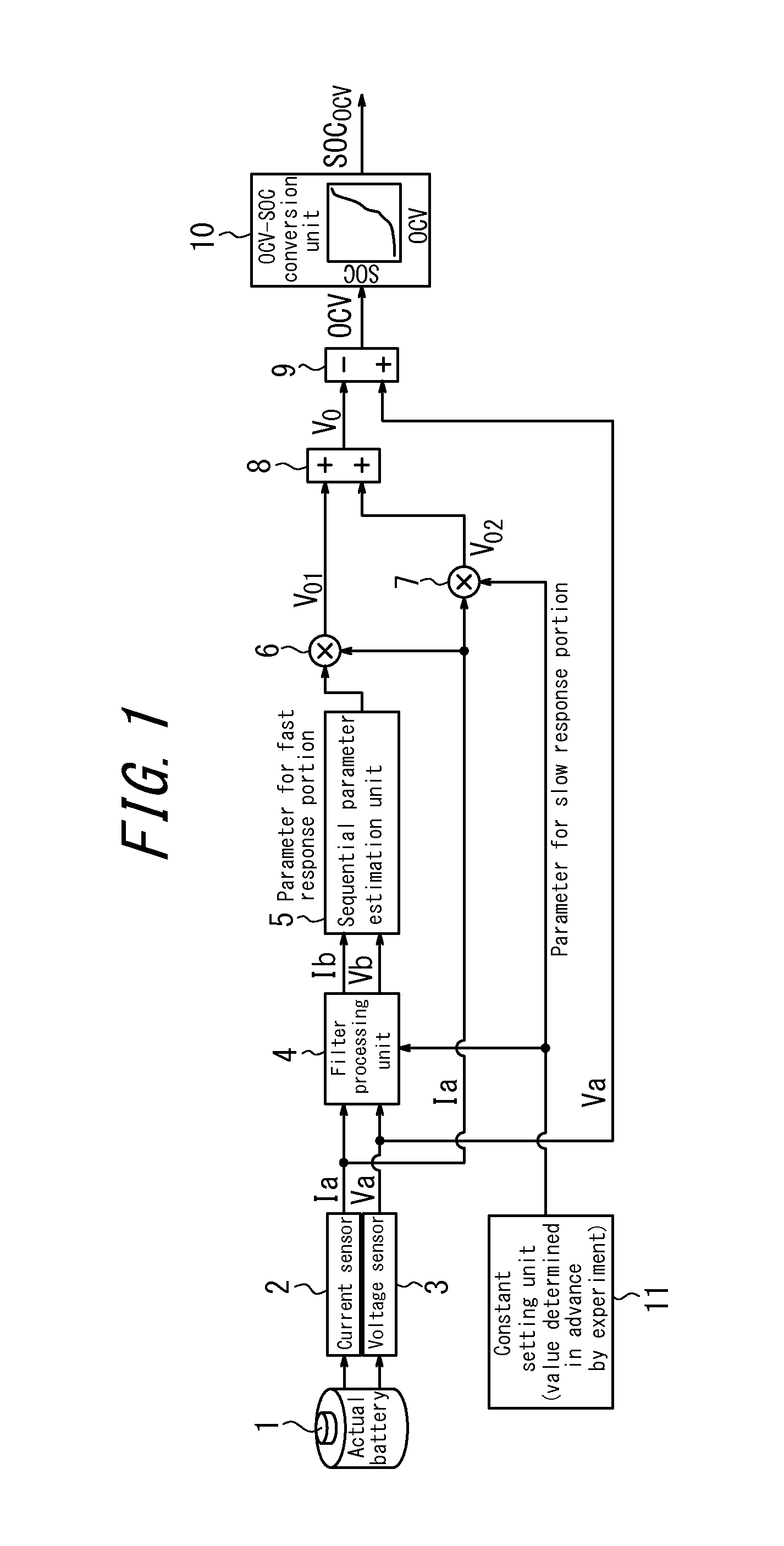
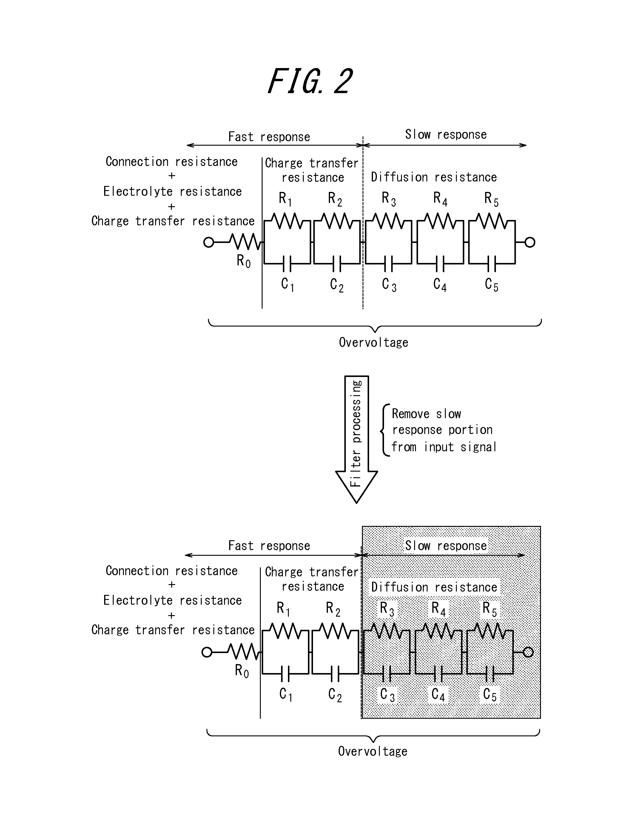
The patent aims to provide an apparatus for battery state estimation that can accurately estimate the internal state of the battery, particularly overvoltage, by taking into consideration the slow response portion of the battery. The apparatus uses sequential parameter estimation to estimate the internal state of the battery, with a constant determined in advance by experiment for the slow response portion. By subtracting the overvoltage value from the terminal voltage value, the apparatus can accurately determine the state of charge. The apparatus also includes a filter processing unit to remove redundant calculation of the overvoltage value in the slow response portion. This improves the estimation accuracy of the battery overvoltage and state of charge.

Problems solved by technology

The above conventional apparatus for state of charge estimation, however, has the problems described below.

Method used


Image

  • Apparatus for battery state estimation
  • Apparatus for battery state estimation
  • Apparatus for battery state estimation

Examples


embodiment 1

[0037]First, the overall structure of the apparatus for battery state estimation according to Embodiment 1 is described.

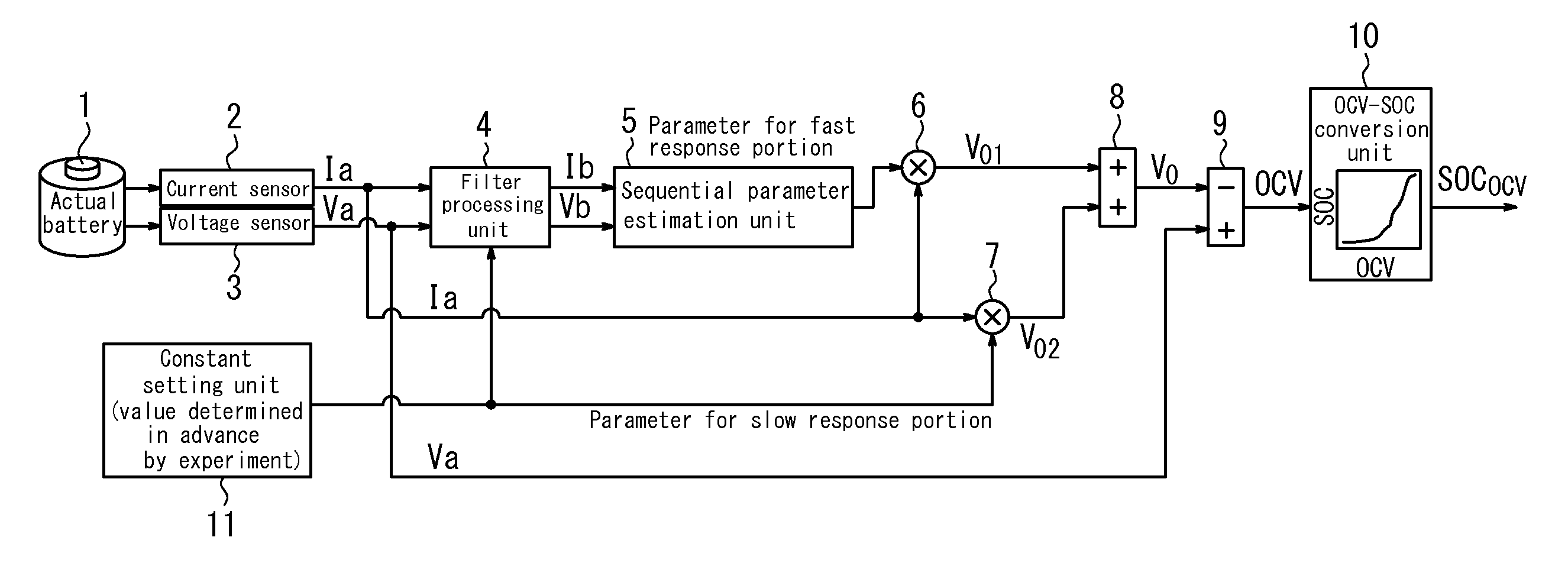
[0038]The apparatus for battery state estimation according to Embodiment 1 is, for example, installed in an electric vehicle and connected to an actual battery 1 (secondary battery such as a lithium-ion battery) that can provide power to a non-illustrated drive motor or the like. This apparatus for state estimation includes a current sensor 2, a voltage sensor 3, a filter processing unit 4, a sequential parameter estimation unit 5, a first multiplier 6, a second multiplier 7, an adder 8, a subtractor 9, an open circuit voltage / state of charge conversion unit 10, and a constant setting unit 11.

[0039]The current sensor 2 detects the magnitude of discharge current when power is being provided from the actual battery 1 to the drive motor or the like. The current sensor 2 also detects the magnitude of charge current when an electric motor is caused to function as an ele...

embodiment 2

[0079]Next, Embodiment 2 is described. In the description of Embodiment 2, structural components similar to Embodiment 1 are not illustrated or are labeled with the same reference signs, and a description thereof is omitted. Only the differences are described.

[0080]As illustrated in FIG. 4, the apparatus for battery internal state estimation according to Embodiment 2 differs from Embodiment 1 in that the filter processing unit 4 of Embodiment 1 in FIG. 1 has been removed. The remaining structure is similar to Embodiment 1.

[0081]The apparatus for battery state estimation according to Embodiment 2 does not include a filter processing unit that removes the overvoltage portion of the slow response portion of the battery, like the low pass filter of Embodiment 1. Therefore, for parameter estimation in the sequential parameter estimation unit 5, a different means is necessary for preventing redundant calculation of the overvoltage value in the slow response portion of the battery.

[0082]Th...


PUM


Abstract

An apparatus for battery state estimation can accurately estimate the internal state of a battery by taking into consideration the slow response portion of the battery. The apparatus for battery state estimation includes a charge / discharge current detection unit, a terminal voltage detection unit, an equivalent circuit model including a fast response portion and slow response portion of the battery, a sequential parameter estimation unit that performs sequential parameter estimation, using only the fast response portion among response portions, based on the charge / discharge current value and the terminal voltage value, a constant setting unit that sets a constant representing resistance and capacitance in the slow response portion of the equivalent circuit model, a plurality of multiplication units that multiply the parameter estimated by the sequential parameter estimation unit and the constant by the charge / discharge current value, and an addition unit that obtains an overvoltage value of the battery by adding the multiplied values.

Description

TECHNICAL FIELD[0001]The present invention relates to an apparatus for battery state estimation that can accurately estimate the internal state of a battery.BACKGROUND ART[0002]Among batteries, rechargeable secondary batteries are for example used in electric vehicles and the like. In this case, it is necessary to know the drivable distance with the battery, the current value at which charge and discharge are possible, and the like, yet to acquire knowledge thereof it is necessary to detect the battery's state of charge (SOC), state of health (SOH), and the like, which are internal state quantities of the battery. However, since these internal state quantities cannot be directly detected, a current integration method (also referred to as a coulomb counting method or a bookkeeping method) or an open circuit voltage estimation method (sequential parameter method) is often used. The current integration method estimates the internal state by detecting the charge / discharge current value ...

Claims


Application Information

Patent Timeline
Patent Type & Authority Applications(United States)
IPC IPC(8): H02J7/00
CPCH02J7/00H01M10/48G01R31/3842G01R31/367G01R31/389Y02E60/10
Inventor ITABASHI, KINNOSUKEADACHI, SHUICHI
Owner CALSONIC KANSEI CORP
Learn More