Automated grounding device with visual indication

Active Publication Date: 2014-11-27
THOMAS & BETTS INT INC
View PDF2 Cites 10 Cited by
  • Summary
  • Abstract
  • Description
  • Claims
  • Application Information

AI Technical Summary

Problems solved by technology

However, this 600 Amp grounding elb

Method used


Image

  • Automated grounding device with visual indication
  • Automated grounding device with visual indication
  • Automated grounding device with visual indication

Examples


Embodiment Construction

[0010]The following detailed description refers to the accompanying drawings. The same reference numbers in different drawings may identify the same or similar elements.

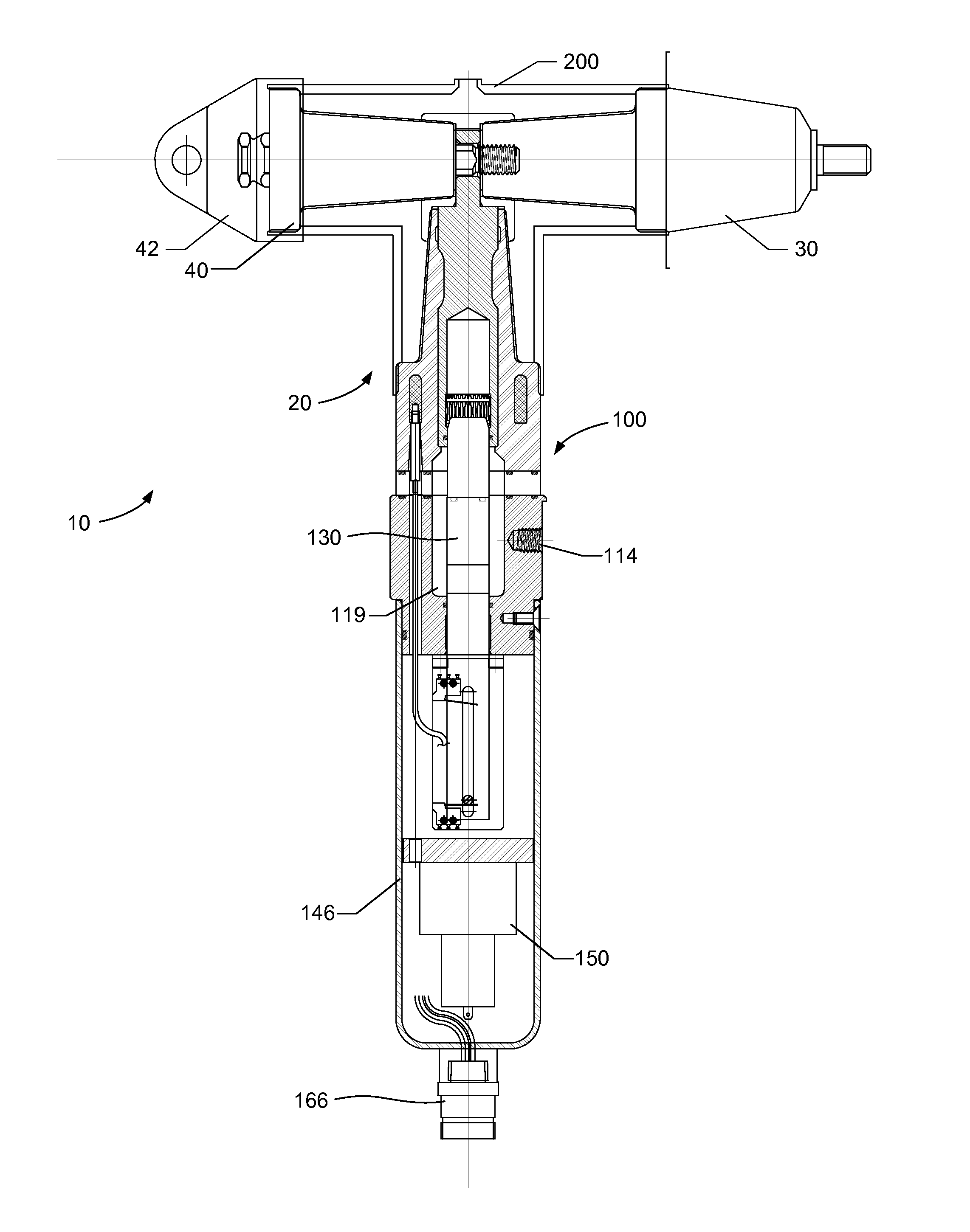
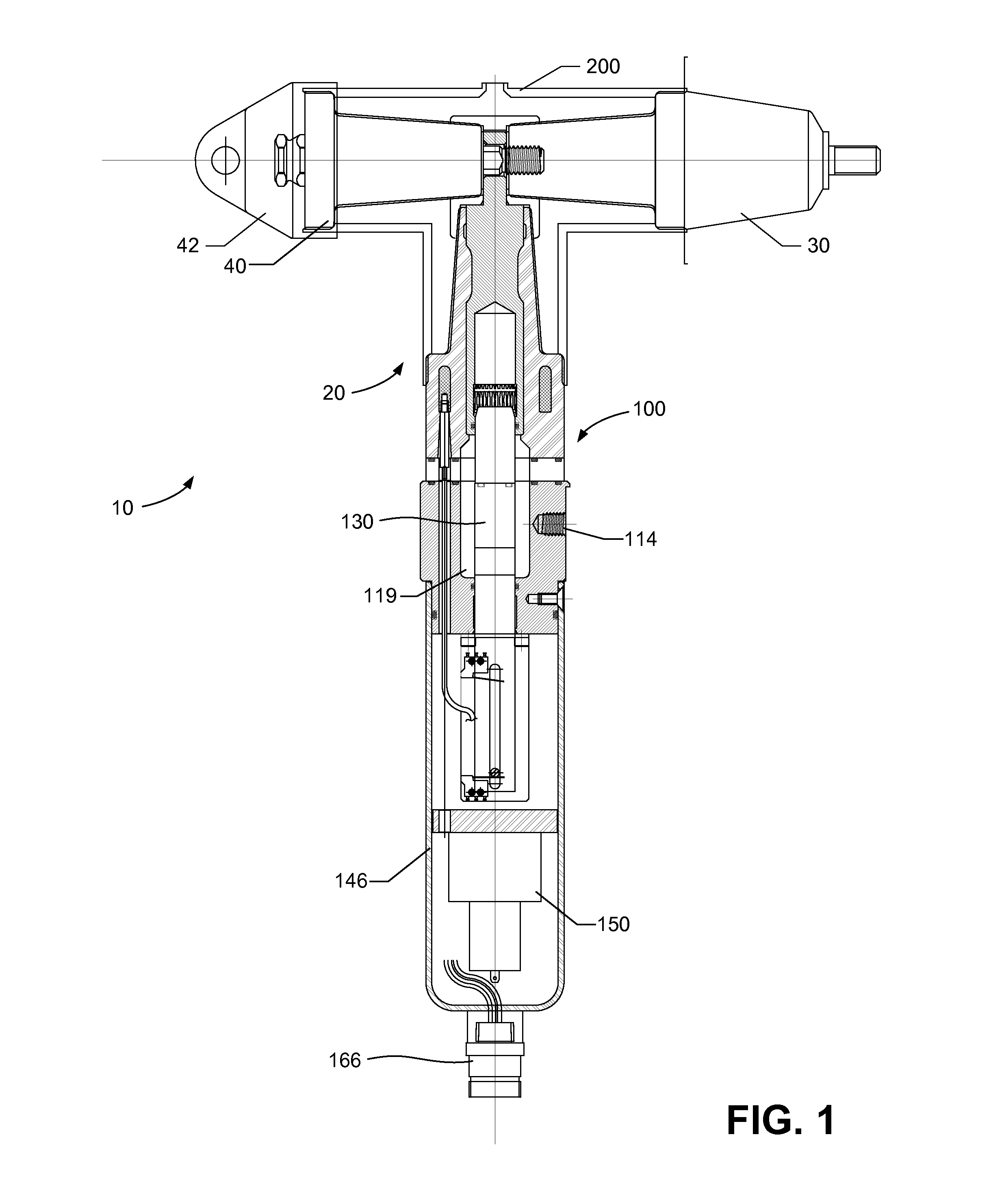
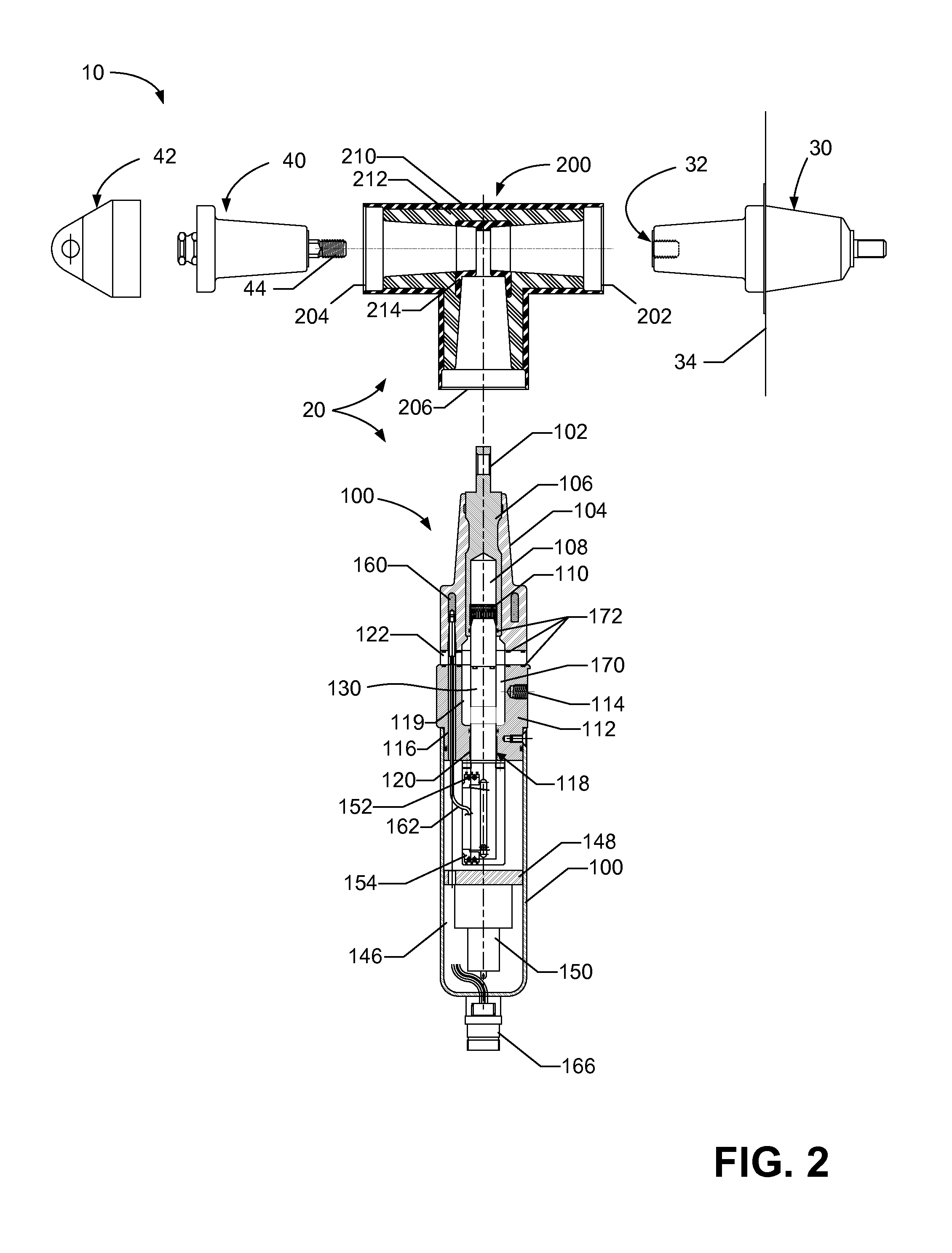
[0011]According to implementations described herein, an automated grounding device is provided for motor-operated switch gear that can be operated at a safe distance. As a visual indication, a viewing window can indicate green (or another color) when contacts in the device are open / ungrounded and yellow (or possible other colors) when contacts in the device are closed / grounded. The device is capable of momentary / fault currents of 25,000 Amps or more, although in some implementations the device may be configured for lower currents, as well. In one implementation, the device uses a clear gel as insulation between contacts to reduce or eliminate the possibility of arcing when the contacts are separated.

[0012]FIG. 1 is a schematic cross-sectional diagram illustrating a side view of an elbow assembly 10 including a ground...


PUM

PropertyMeasurementUnit
Distanceaaaaaaaaaa
Distanceaaaaaaaaaa
Currentaaaaaaaaaa

Abstract

A grounding device for switchgear includes a connector and a body. The body includes (1) a male interface portion including an electrically conductive bus with a first bore and a spade connector; (2) a conductive housing including a second bore that is axially aligned with the first bore, and a grounding terminal to receive a grounding wire; (3) a pin assembly including a non-conductive tip, and a conductive pin, wherein the pin assembly is configured to move axially within the first and second bores between a closed position that provides an electrical connection between the bus and the conductive housing and an open position that provides no electrical connection; (4) a communications receptacle to receive signals from a controller outside the device body; and (5) a motor configured to selectively drive the pin assembly between the open position and the closed position, based on a signal from the controller.

Description

CROSS-REFERENCE TO RELATED APPLICATION[0001]This application claims priority under 35 U.S.C. §119, based on U.S. Provisional Patent Application No. 61 / 827,381 filed May 24, 2013, the disclosure of which is hereby incorporated by reference herein.BACKGROUND OF THE INVENTION[0002]The present invention relates to grounding devices for high voltage electrical switchgear. Generally, utility workers are instructed not to open high voltage switch gear cabinets unless they are sure the circuit is de-energized. This is accomplished via the connectors on the outside of the switch gear. Currently, there are two primary ways of grounding a high voltage connector attached to the dead front of a switch gear apparatus. The first is the use of a 200 Amp grounding elbow that is coupled to ground. The 200 Amp elbow is attached using a hotstick for safety. This elbow only has a 10,000 Amp rating, which could be exceeded by today's high current circuits. The second way to ground the connector is by usi...

Claims


Application Information

Patent Timeline
IPC IPC(8): H01H9/12H01H11/00
CPCH01H11/00H01H9/12G01R15/16H01H9/16H01H31/003H01H2009/0292H01R13/53H01R31/02Y10T29/49105
Inventor SIEBENS, LARRY N.
Owner THOMAS & BETTS INT INC
Why Eureka
Try Eureka