Multi charged particle beam writing apparatus, and multi charged particle beam writing method

a writing apparatus and charged particle technology, applied in the field of multi-charged particle beam writing apparatus and multi-charged particle beam writing method, can solve the problems of short writing time, long writing time, and limit of this method

Active Publication Date: 2014-11-27
NUFLARE TECH INC
View PDF4 Cites 21 Cited by
  • Summary
  • Abstract
  • Description
  • Claims
  • Application Information

AI Technical Summary

Problems solved by technology

In a variable shaped beam (VSB) type electron beam writing that uses a single electron beam for writing, the more patterns become complicated, the more it becomes necessary to divide patterns into fine shot figures, so that the writing time becomes long.
However, if this method is employed, since the influence of resist heating and the like becomes large, there is a limit also to this method.
Therefore, the writing time is short in the case of layout with low pattern density.
However, the lower the layout pattern density is, the larger the dose needed for exposure becomes.

Method used


Image

  • Multi charged particle beam writing apparatus, and multi charged particle beam writing method
  • Multi charged particle beam writing apparatus, and multi charged particle beam writing method
  • Multi charged particle beam writing apparatus, and multi charged particle beam writing method

Examples


first embodiment

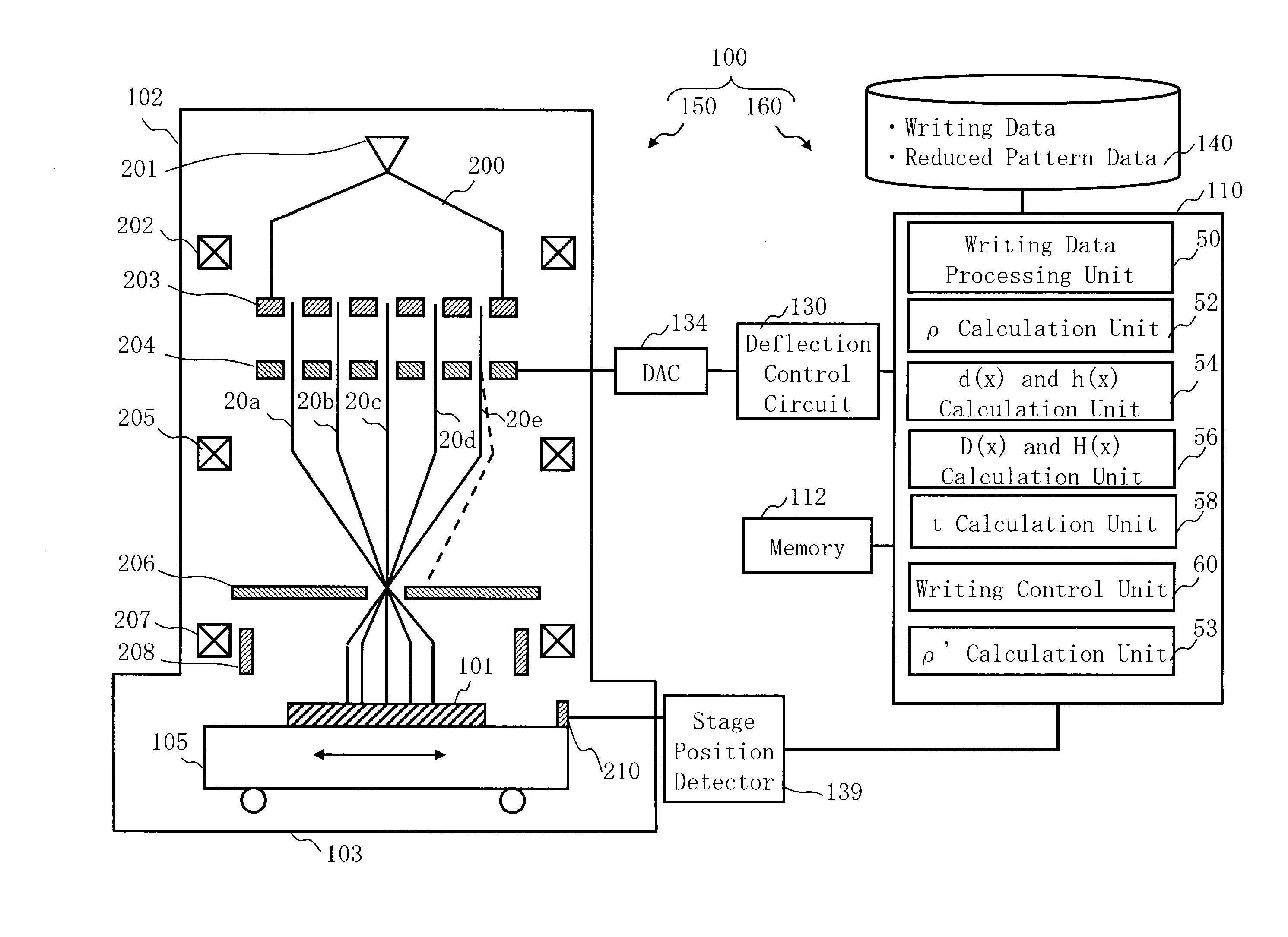
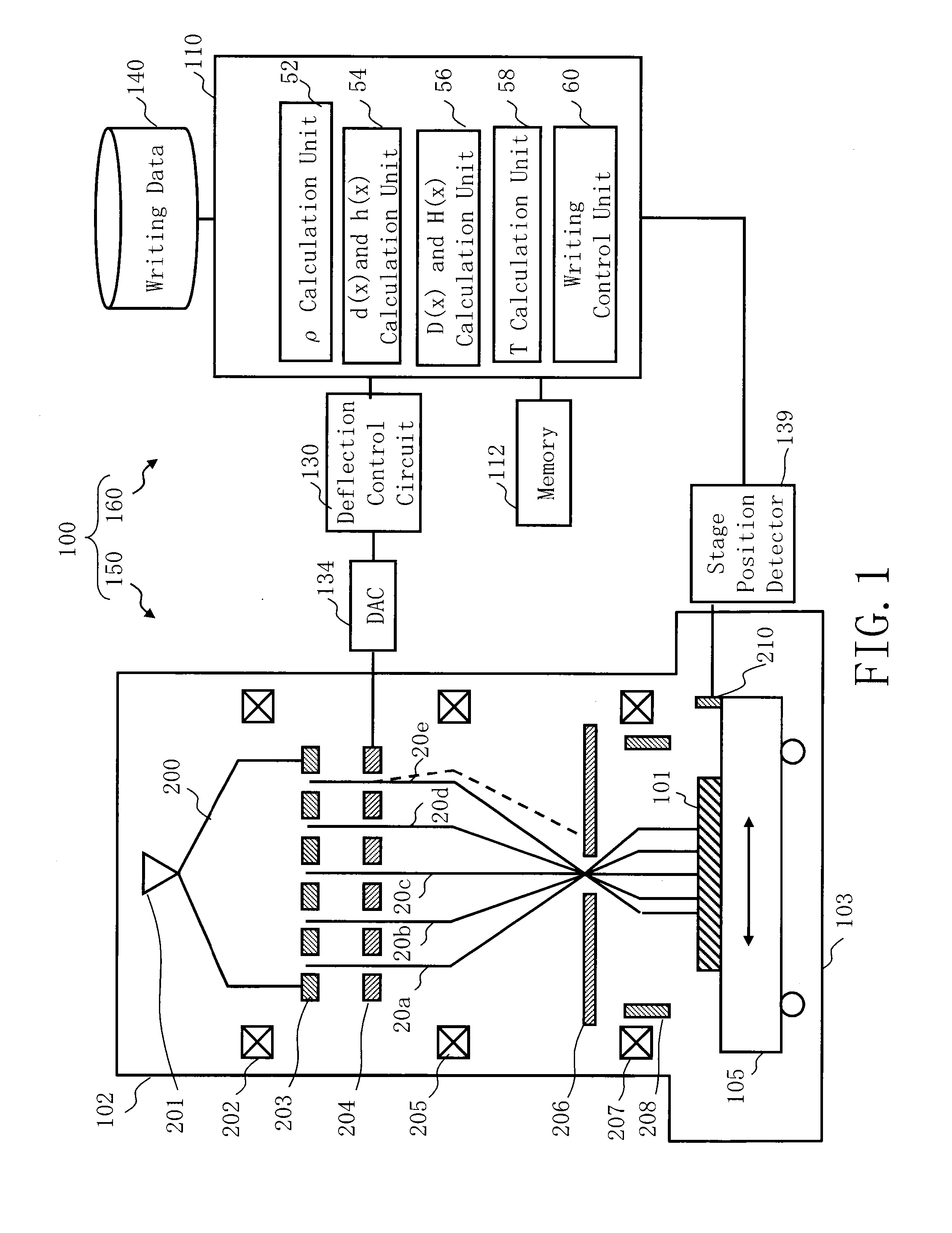
[0032]FIG. 1 is a schematic diagram showing a configuration of a writing apparatus according to the first embodiment. As shown in FIG. 1, a writing (or “drawing”) apparatus 100 includes a writing unit 150 and a control unit 160. The writing apparatus 100 is an example of a multi charged particle beam writing apparatus. The writing unit 150 includes an electron optical column 102 and a writing chamber 103. In the electron optical column 102, there are arranged an electron gun assembly 201, an illumination lens 202, an aperture member 203, a blanking plate 204, a reducing lens 205, a limiting aperture member 206, an objective lens 207, and a deflector 208. In the writing chamber 103, there is arranged an XY stage 105. On the XY stage 105, a target object or “sample”101 such as a mask serving as a writing target substrate is placed when performing writing. The target object 101 is, for example, an exposure mask used for manufacturing semiconductor devices, or a semiconductor substrate ...

second embodiment

[0058]In the above first embodiment, the region in which no figure pattern is arranged and which surrounds the whole perimeter of a figure pattern and is irradiated by the beam is defined as a region in contact with the figure pattern, but it is not limited thereto. The second embodiment describes other cases.

[0059]FIG. 12 is a schematic diagram showing a structure of a writing apparatus according to the second embodiment. The writing apparatus 100 of FIG. 12 is the same as that of FIG. 1 except that the writing data processing unit 50 and a pattern density calculation unit 53 are added in the control computer 110, and that reduced pattern data is stored in the storage device 140.

[0060]FIG. 13 is a flowchart showing main steps of a writing method according to the second embodiment. FIG. 13 is the same as FIG. 9 except that a pattern density map generation step (S103) is added before the dose coefficient calculation step (S104). The content of the second embodiment is the same as tha...

third embodiment

[0074]In the first embodiment as mentioned above, the coefficient β of the equation (1-2) is described in the range of a specified value. However, the value of the coefficient β is not limited to the case of being a certain value in a series of steps. Another case will be explained in the third embodiment.

[0075]FIG. 17 is a schematic diagram showing a structure of a writing apparatus according to the third embodiment. The writing apparatus 100 of FIG. 17 is the same as that of FIG. 1 except that a β calculation unit 53 is added in the control computer 110, and a storage device 142 such as a magnetic disk is added.

[0076]FIG. 18 is a flowchart showing main steps of a drawing method according to the third Embodiment. FIG. 18 is the same as FIG. 9 except that a β map generation step (S103) is added before the dose coefficient calculation step (S104). The content of the third embodiment is the same as that of the first embodiment except what is particularly described below.

[0077]FIG. 19 ...


PUM


Abstract

A multi charged particle beam writing apparatus includes a dose calculation unit to calculate a first dose resolving the resist of the target object, for a first beam of the multiple beams, corresponding to a pattern forming region, in which a pattern is arranged, and to calculate a second dose not resolving the resist, for a second beam of the multiple beams, corresponding to a no-pattern forming region, which surrounds the whole perimeter of the pattern and in which no pattern is arranged, and a deflection control unit to control a plural blankers so that a dose of the first beam is to be the first dose calculated and a dose of the second beam is to be the second dose calculated.

Description

CROSS-REFERENCE TO RELATED APPLICATION[0001]This application is based upon and claims the benefit of priority from the prior Japanese Patent Application No. 2013-109839 filed on May 24, 2013 in Japan, the entire contents of which are incorporated herein by reference.BACKGROUND OF THE INVENTION[0002]1. Field of the Invention[0003]The present invention relates to a multi charged particle beam writing apparatus and a multi charged particle beam writing method. More specifically, for example, the present invention relates to a method for reducing the time of writing with multiple beams.[0004]2. Description of Related Art[0005]The lithography technique that advances miniaturization of semiconductor devices is extremely important as being a unique process whereby patterns are formed in the semiconductor manufacturing. In recent years, with high integration of LSI, the line width (critical dimension) required for semiconductor device circuits is decreasing year by year. The electron beam (...

Claims


Application Information

Patent Timeline
Patent Type & Authority Applications(United States)
IPC IPC(8): H01J37/317H01J37/20H01J37/30
CPCH01J37/3177H01J37/20H01J37/3007H01J37/3175H01J2237/31754H01J2237/31774H01L21/0274H01L21/0275H01J37/045H01J37/243
Inventor MATSUMOTO, HIRONOBU
Owner NUFLARE TECH INC
Why Eureka
Try Eureka